This manual confers no industrial property rights or any rights of any other kind,
nor does it confer any patent licenses. Mitsubishi Electric Corporation cannot be
held responsible for any problems involving industrial property rights which may
occur as a result of using the contents noted in this manual.
Warranty
Mitsubishi will not be held liable for damage caused by factors found not to be
the cause of Mitsubishi; opportunity loss or lost profits caused by faults in the
Mitsubishi products; damage, secondary damage, accident compensation
caused by special factors unpredictable by Mitsubishi; damages to products
other than Mitsubishi products; and to other duties.
For safe use
This product has been manufactured as a general-purpose part for general
industries, and has not been designed or manufactured to be incorporated in
a device or system used in purposes related to human life.
Before using the product for special purposes such as nuclear power, electric
power, aerospace, medicine or passenger movement vehicles, consult with
Mitsubishi Electric.
This product has been manufactured under strict quality control. However
when installing the product where major accidents or losses could occur if the
product fails, install appropriate backup or failsafe functions in the system.
HEAD OFFICE : TOKYO BUILDING, 2-7-3 MARUNOUCHI, CHIYODA-KU, TOKYO 100-8310, JAPAN
Side
A
Side
B
JAPANESE
ENGLISH
JY997D50601B
Side
B
FX
2N
-1PG-E
INSTALLATION MANUAL
This manual describes the part names, dimensions, mounting, wiring, and
specifications of the product. Before use, read this manual and the manuals of all
relevant products fully to acquire proficiency in handling and operating the
product. Make sure to learn all the product information, safety information, and
precautions.
Store this manual in a safe place so that it can be taken out and read whenever
necessary. Always forward it to the end user.
Registration:
The company and product names described in this manual are registered
trademarks or the trademarks of their respective companies.
Effective April 2015
Specifications are subject to change without notice.
2013 Mitsubishi Electric Corporation
Manual Number JY997D50601
Revision B
Date April 2015
Safety Precaution
(Read these precautions before use.)
This manual classify the safety precautions into two categories:
and .
Depending on circumstances, procedures indicated by may also be
linked to serious results.
In any case, it is important to follow the directions for usage.
Associated Manuals
Indicates that incorrect handling may cause hazardous
conditions, resulting in death or severe injury.
Indicates that incorrect handling may cause hazardous
conditions, resulting in medium or slight personal injury
or physical damage.
Manual name Manual No. Description
FX
2N
-1PG/FX-1PG
User’s Manual
JY992D65301
MODEL CODE:
09R610
Describes FX
2N
-1PG/FX-1PG pulse
output block details.
FX
3U
Series
User’s Manual
- Hardware Edition
JY997D16501
MODEL CODE:
09R516
Explains FX
3U
Series PLC
specification details for I/O, wiring,
installation, and maintenance.
FX
3UC
Series
User’s Manual
- Hardware Edition
JY997D28701
MODEL CODE:
09R519
Explains FX
3UC
Series PLC
specification details for I/O, wiring,
installation, and maintenance.
FX
2N
HARDWARE MANUAL
JY992D66301
MODEL CODE:
09R508
Explains FX
2N
Series PLC
specification details for I/O, wiring,
installation, and maintenance.
FX
2NC
(D/UL)
HARDWARE MANUAL
JY992D87201
Explains FX
2NC
(D/UL) Series PLC
specification details for I/O, wiring,
installation, and maintenance.
FX
2NC
(DSS/DS)
HARDWARE MANUAL
JY992D76401
MODEL CODE:
09R509
Explains FX
2NC
(DSS/DS) Series
PLC specification details for I/O,
wiring, installation, and maintenance.
FX
3S
/FX
3G
/FX
3GC
/
FX
3U
/FX
3UC
Series
Programming Manual
- Basic & Applied
Instruction Edition
JY997D16601
MODEL CODE:
09R517
Describes PLC programming for
basic/applied instructions and
devices.
How to obtain manuals
For the necessary product manuals or documents, consult with the Mitsubishi Electric
dealer from where you purchase your product.
Certification of UL, cUL standards
FX
2N
-1PG-E units comply with the UL standards (UL, cUL).
UL, cUL File Number: E95239
Regarding the standards that comply with the main unit, please refer to either the FX
series product catalog or consult with your nearest Mitsubishi product provider.
Compliance with EC directive (CE Marking)
This document does not guarantee that a mechanical system including this product will
comply with the following standards.
Compliance to EMC directive and LVD directive for the entire mechanical module
should be checked by the user/manufacturer. For more information please consult with
your nearest Mitsubishi product provider.
Requirement for Compliance with EMC directive
The following products have shown compliance through direct testing (of the identified
standards below) and design analysis (through the creation of a technical construction
file) to the European Directive for Electromagnetic Compatibility (2004/108/EC) when
used as directed by the appropriate documentation.
Attention
This product is designed for use in industrial applications.
Note
Authorized Representative in the European Community:
Mitsubishi Electric Europe B.V.
Gothaer Str. 8, 40880 Ratingen, Germany
Type: Programmable Controller (Open Type Equipment)
Models: MELSEC FX
2N
series manufactured
from September 1st, 1997 FX
2N
-1PG-E
*1 FX
2N
-1PG-E products produced before July 31 2010 comply with EN61131-2:2003.
Caution for EC Directive
Notes for compliance with EN61131-2:2007
General notes on the use of the power supply cable.
The FX
2N
-1PG-E unit require that the cable used for power supply is 30 m or less.
1. Outline
1.1 Outline
The FX
2N
-1PG-E pulse output block performs simple positioning of an independent
axis (not interpolation control between multiple axes) by supplying a prescribed
quantity of pulses (100 kHz maximum) to drive amplifiers for servo or stepper motors.
1.2 Incorporated Items
Check if the following product and items are included in the package:
Standard Remark
EN61131-2:2007
*1
Programmable controllers
- Equipment requirements
and tests
Compliance with all relevant aspects of the
standard.
EMI
• Radiated Emission
• Conducted Emission
EMS
• Radiated electromagnetic field
• Fast transient burst
• Electrostatic discharge
• High-energy surge
• Voltage drops and interruptions
• Conducted RF
• Power frequency magnetic field
Included Items
FX
2N
-1PG-E 1 unit
No. labels for special modules 1 sheet
Dust proof protection sheet 1 sheet
Manuals (Japanese/English) 1 manual
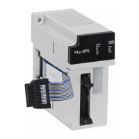
1.3 External Dimensions, Part Names
1.4 Status LED
[1] Status LEDs (red) [6] DIN rail mounting groove
(DIN rail: DIN46277,
35 mm (1.38") width)
[2] Extension cable
[3] Power LED (green) [7] DIN rail mounting hook
[4] Direct mounting hole
2 holes of
4.5 (0.18”)
(mounting screw: M4 screw)
[8] Terminal block (M3 screw)
[9] Extension connector
[5] Name plate
LED
Display
Description
POWER
Indicates power status of FX
2N
-1PG-E.
Lighted when 5 V is supplied from PLC.
STOP Lighted when the stop command is input to the STOP terminal.
DOG Lighted when DOG input is entered.
PG0 Lighted when zero point signal is entered.
FP
Flashes when forward pulse or pulses
are output.
Output format can be
modified using BFM#3 b8.
RP
Flashes when reverse pulse is output.
Lighted when direction is output.
CLR Lighted when CLR signal is output.
ERR
Flashes when error has occurred.
Start command is not accepted when error has occurred.
[Without top cover]
[2]
[4]
[1]
[5]
[8]
[8]
[9]
[6]
[7]
[3]
Unit: mm (inches)
MASS (Weight): Approx. 0.2 kg (0.44 lbs)
87 (3.43")43 (1.7")
4 (0.16")
90 (3.55")
2-4.5 mounting holes
80 (3.15")
(mounting hole pitch)
1.5 Terminal Layout
1.5.1 Terminal screws and tightening torque
For the terminals of FX
2N
-1PG-E, M3 screws are used.
Tighten the screws to a torque of 0.5 to 0.8 N
m.
Do not tighten terminal screws with a torque exceeding the regulation torque.
Failure to do so may cause equipment failures or malfunctions.
For details on the wiring needed to connect to the terminal blocks shown in the
figure above, refer to the following manual.
Refer to FX
2N
-1PG/FX-1PG User's Manual.
Terminal
Name
Description
VIN Power terminal for pulse output (5 to 24 V DC, 35 mA or less)
COM0 Common terminal for pulse output
FP
Terminal which outputs forward pulse or pulses.
100 kHz, 20 mA or less (5 to 24 V DC)
RP
Terminal which outputs reverse pulse or direction.
100 kHz, 20 mA or less (5 to 24 V DC)
PG0-
Enters zero point signal from drive unit or servo amplifier.
Response pulse width: 4 s or more
PG0+ Power terminal for zero point signal. (5 to 24 V DC, 20 mA or less)
COM1 Common terminal for CLR output
CLR
Output for clearing deviation counter. (5 to 24 V DC, 20 mA or less)
Output pulse width: 20 ms (Output when return to home position is
completed or LIMIT SWITCH input is given.)
S/S
24 V DC power terminal for STOP input and DOG input.
Connected to sensor power supply of PLC or external power supply.
STOP
DECELERATION STOP input.
Can function as stop command input in external command
operation mode.
DOG
Offers following different functions depending on operation mode.
Machine home position return operation: NEAR POINT SIGNAL
input
Interrupt single-speed operation: INTERRUPT input
External command operation: DECELERATION START input
STOP
DOG
S/SS/S
COM1
CLRRP
PG0+
PG0-FPVIN
COM0
2. Installation
2.1 Connection with PLC
The FX
2N
-1PG-E connects on the right side of an PLC main unit or extension
units/blocks (including special function units/blocks).
For connection to an FX
3UC
Series, FX
2NC
Series PLC or FX
2NC
Series PLC
extension block, an FX
2NC
-CNV-IF or FX
3UC
-1PS-5V is required.
For details, refer to the respective PLC manual.
Refer to FX
2N
HARDWARE MANUAL.
Refer to FX
2NC
HARDWARE MANUAL.
Refer to FX
3U
Series User's Manual - Hardware Edition.
Refer to FX
3UC
Series User's Manual - Hardware Edition.
2.2 Mounting
The product is mounted by the following method.
DIN rail mounting
Direct mounting (mounting screw: M4 screw)
For details, refer to the respective PLC manual.
Refer to FX
2N
HARDWARE MANUAL.
Refer to FX
2NC
HARDWARE MANUAL.
Refer to FX
3U
Series User's Manual - Hardware Edition.
Refer to FX
3UC
Series User's Manual - Hardware Edition.
3. Specifications
INSTALLATION
PRECAUTIONS
Make sure to cut off all phases of the power supply externally before
attempting installation or wiring work.
Failure to do so may cause electric shock or damage to the product.
INSTALLATION
PRECAUTIONS
Use the product within the generic environment specifications described in
PLC main unit manual.
Never use the product in areas with excessive dust, oily smoke, conductive
dusts, corrosive gas (salt air, Cl
2
, H
2
S, SO
2
, or NO
2
), flammable gas,
vibration or impacts, or expose it to high temperature, condensation, or rain
and wind.
If the product is used in such conditions, electric shock, fire, malfunctions,
deterioration or damage may occur.
Do not touch the conductive parts of the product directly.
Doing so may cause device failures or malfunctions.
Install the product securely using a DIN rail or mounting screws.
Install the product on a flat surface.
If the mounting surface is rough, undue force will be applied to the PC board,
thereby causing nonconformities.
When drilling screw holes or wiring, make sure that cutting and wiring debris
do not enter the ventilation slits.
Failure to do so may cause fire, equipment failures or malfunctions.
Be sure to remove the dust proof sheet from the PLC's ventilation port when
installation work is completed.
Failure to do so may cause fire, equipment failures or malfunctions.
Make sure to attach the top cover, offered as an accessory, before turning on
the power or initiating operation after installation or wiring work.
Failure to do so may cause electric shock.
Connect the extension cables securely to their designated connectors.
Loose connections may cause malfunctions.
DESIGN
PRECAUTIONS
Make sure to have the following safety circuits outside the PLC to ensure
safe system operation even during external power supply problems or PLC
failure.
Otherwise, malfunctions may cause serious accidents.
1) Most importantly, have the following: an emergency stop circuit, a
protection circuit, an interlock circuit for opposite movements (such as
normal vs. reverse rotation), and an interlock circuit (to prevent damage
to the equipment at the upper and lower positioning limits).
2) Note that when the PLC CPU detects an error, such as a watchdog timer
error, during self-diagnosis, all outputs are turned off. Also, when an error
that cannot be detected by the PLC CPU occurs in an input/output control
block, output control may be disabled.
External circuits and mechanisms should be designed to ensure safe
machinery operation in such a case.
3) Note that when an error occurs in a relay, triac or transister output device,
the output could be held either on or off.
For output signals that may lead to serious accidents, external circuits
and mechanisms should be designed to ensure safe machinery operation
in such a case.
3.1 Applicable PLC
*1 An FX
2NC
-CNV-IF or FX
3UC
-1PS-5V is necessary to connect the FX
2N-
1PG with
the FX
3UC
PLC or FX
2NC
PLC.
*2 Up to 7 units can be connected to the FX
3UC
-32MT-LT(-2) PLC.
3.2 General Specifications
The general specifications are equivalent to those of the main unit of the FX PLC.
For general specifications, refer to the manual of the PLC main unit.
Refer to FX
2N
HARDWARE MANUAL.
Refer to FX
2NC
HARDWARE MANUAL.
Refer to FX
3U
Series User's Manual - Hardware Edition.
Refer to FX
3UC
Series User's Manual - Hardware Edition.
3.3 Performance Specifications
DESIGN
PRECAUTIONS
Make sure to observe the following precautions in order to prevent any damage to
the machinery or accidents due to abnormal data written to the PLC under the
influence of noise:
1) Do not bundle the main circuit line together with or lay it close to the main
circuit, high-voltage line or load line.
Otherwise, noise disturbance and/or surge induction are likely to take place.
As a guideline, lay the control line at least 100 mm (3.94") or more away from
the main circuit or high-voltage lines.
2) Ground the shield wire or shield of a shielded cable. Do not use common
grounding with heavy electrical systems.
Install module so that excessive force will not be applied to the terminal blocks.
Failure to do so may result in wire damage/breakage or PLC failure.
WIRING
PRECAUTIONS
Make sure to cut off all phases of the power supply externally before attempting
installation or wiring work.
Failure to do so may cause electric shock or damage to the product.
WIRING
PRECAUTIONS
Connect the DC power supply wiring to the dedicated terminals described in this
manual.
If an AC power supply is connected to a DC input/output terminal or DC power
supply terminal, the PLC will burn out.
Make sure to attach the top cover, offered as an accessory, before turning on the
power or initiating operation after installation or wiring work.
Failure to do so may cause electric shock.
When drilling screw holes or wiring, make sure cutting or wire debris does not
enter the ventilation slits.
Failure to do so may cause fire, equipment failures or malfunctions.
Make sure to properly wire the extension equipment in accordance with the
following precautions.
Failure to do so may cause electric shock, equipment failures, a short-circuit, wire
breakage, malfunctions, or damage to the product.
- The disposal size of the cable end should follow the dimensions described in
the manual.
- Tightening torque should follow the specifications in the manual.
DISPOSAL
PRECAUTIONS
Please contact a certified electronic waste disposal company for the
environmentally safe recycling and disposal of your device.
TRANSPORTATION AND
STORAGE PRECAUTIONS
The PLC is a precision instrument. During transportation, avoid impacts larger
than those specified in the general specifications of the PLC main unit manual.
Failure to do so may cause failures in the PLC.
After transportation, verify the operations of the PLC.
Model name Maximum number of connectable units
FX
2N
Series PLC 8 units
FX
2NC
Series PLC
*1
4 units
FX
3U
Series PLC 8 units
FX
3UC
Series PLC
*1
8 units
*2
Item Specifications
Drive power
supply
+24V (for input signals): 24 V DC ±10% Current consumption:
40 mA or less
+5V (for internal control): 5 V DC, 55 mA Supplied from PLC
via extension cable.
For pulse output: 5 V to 24 V DC current consumption: 35 mA
or less
*1 One zero point signal PG0 is entered by flowing the current from the PG0+
terminal to the PG0- terminal.
*2 FX
3U
/FX
3UC
Series PLC can use direct specification of buffer memory. Refer to
the FX
3S
/FX
3G
/FX
3GC
/FX
3U
/FX
3UC
Series Programming Manual - Basic &
Applied Instruction Edition for details.
3.4 Input Specifications and Wiring Example
3.4.1 Input specifications
3.4.2 Input wiring example
Number of I/O
points occupied
8 input or output points of PLC for each FX
2N
-1PG-E
Number of
control axes
One axis
Command
speed
Operations are enabled at pulse speed of 10 Hz to 100 kHz.
Command unit can be selected among Hz, cm/min,
10 deg/min and inch/min.
Setting pulse
0 to ± 999.999
Absolute position specification or relative travel specification
can be selected.
Command unit can be selected among pulse, μm, mdeg and
10
-4
inch.
Multiplication of 10
0
, 10
1
, 10
2
or 10
3
can beset for position
data.
Pulse output
format
Forward (FP) and reverse (RP) pulse or pulse (PLS) with
direction (DIR) can be selected.
Transistor output. 5 to 24 V DC, 20 mA or less
External I/O
Photocoupler insulation and LED operation indication are
offered for every point.
3 input points: (STOP/DOG) 24 V DC, 7 mA and (PG0
*1
) 24 V
DC, 20 mA
3 output points (FP/RP/CLR): 5 to 24 V DC, 20 mA or less
(For details, refer to FX
2N
-1PG/FX-1PG User’s Manual.)
Communication
with PC
16-bit RAM (without battery backup) buffer memories (BFMs) #0
to #31 are built in FX
2N
-1PG-E.
Data communication with PC is performed using FROM/TO
instructions
*2
.
32-bit data is processed by combining two BFMs.
(For details, refer to FX
2N
-1PG/FX-1PG User’s Manual.)
Item Specifications
S/S
DOG
STOP
PG0+
PG0-
Connected to 24 V DC service power supply
of PLC or external power supply
24 V DC, 7 mA Response lag: 1 ms
Input ON current: 4.5 mA or more
Input OFF current: 1.5 mA or less
24 V DC, 7 mA Response lag: 4 ms
Input ON current: 4.5 mA or more
Input OFF current: 1.5 mA or less
5 to 24 V DC, 20 mA or less
Input ON current: 4 mA or more
Input OFF current: 0.5 mA or less
Response pulse width: 4 μs or more
FX
2N
-1PG-E
S/S
DOG
STOP
Servo amplifier
PG0+
PG0-
FX
2N
-1PG-E
3.5 Output Specifications and Wiring Example
3.5.1 Output specifications
3.5.2 Output wiring example
VIN
FP
RP
COM0
COM1
CLR
5 to 24 V DC
Current consumption: 35 mA or less
100 kHz pulse output,
5 to 24 V DC, 20 mA or less
100 kHz pulse output,
5 to 24 V DC, 20 mA or less
Output for clearing deviation counter
5 to 24 V DC, 20 mA or less
Output pulse width: 20 ms
(When home position return is completed or
limit switch is input)
FX
2N
-1PG-E
VIN
FP
RP
COM0
COM1
CLR
Servo amplifier
FX
2N
-1PG-E
Industrial
automation
Elincom
Group
European
Union:
www.elinco.eu
Russia:
www.elinc.ru