


S
Stephen BeckerSep 2, 2025
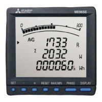
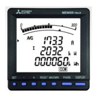
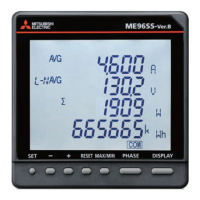
Why is the total RMS value of harmonic current quite different from the current value on Mitsubishi Electric ME96SSRB-MB?
- DDaniel CabreraSep 2, 2025
The distortion ratio (content rate) is well over 100%. Check the measured item.