Do you have a question about the Mitsubishi Electric MEHP-iB-G07 and is the answer not in the manual?
| Model | MEHP-iB-G07 |
|---|---|
| Category | Heat Pump |
| Refrigerant | R410A |
| Power Supply | 220-240 V, 50 Hz |
| Operating Temperature Range (Heating) | -15°C to 24°C |
| Noise Level (Outdoor Unit) | 52 dB |
Explains danger symbols indicating severe hazards.
Explains warning symbols for potentially fatal hazards.
Explains attention symbols for minor damage hazards.
Explains notice symbols for non-injury related practices.
Explains obligation symbols for mandatory actions.
Primary manual for product installation, operation, and maintenance.
Guides for operating the electronic controller or quick usage.
Provides detailed measurements and physical specifications of the unit.
Illustrates the refrigerant circuit and its components.
Details the water or fluid circuit connections and layout.
Shows the electrical connections and component layout.
Confirms compliance with EU directives for the unit.
Contains technical data, specifications, and performance information.
Notes regarding changes and modifications to technical documentation.
Mandatory requirement to read and understand manuals before operation.
Details on the unit's identification, specifications, and manufacturing data.
Explanation of the model naming convention and its components.
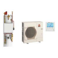
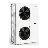
Overview of the unit's function, design, and key features.
Conditions and limitations of the unit's warranty coverage.
Procedure for checking the unit upon delivery for damage or missing parts.
Steps to follow when an alarm occurs and how to reset it.
Information on the unit's expected operational lifespan and maintenance.
Requirement to read and understand the manual before operating the unit.
Identifies residual risks and the required Personal Protective Equipment (PPE).
Defines key terms and the roles of personnel involved with the unit.
Specifies who can access the unit and under what conditions.
Measures to mitigate mechanical and electrical risks during operation.
General safety precautions for non-specific risks.
Hazards associated with refrigerant gases and fluids and necessary precautions.
Information on R32 refrigerant, its flammability, and safety data.
First aid and handling procedures for refrigerants and other fluids.
Precautions regarding flammable materials and fire hazards near the unit.
General safety guidelines for unit operation and maintenance.
Details on refrigerants' environmental impact (GWP) and disposal.
Procedures for checking the unit upon delivery and proper storage methods.
Guidelines for safely moving, lifting, and placing the unit.
Methods for lifting the unit using forklifts or cranes while packaged.
Instructions for safely removing the unit's packaging and its disposal.
Procedures for handling the unit once packaging has been removed.
Required spatial clearances for unit installation and airflow.
Guidance on selecting an appropriate and safe location for unit installation.
Key points to consider and agree upon before installing the unit.
Specific instructions for correctly positioning the unit on its support.
Detailed dimensions and weights for specific unit models.
Detailed dimensions and weights for specific unit models.
Detailed dimensions and weights for specific unit models.
Safe management and design considerations for hydraulic circuits with R32.
Specifications and diagrams for hydraulic connections.
Required water volume in the system to prevent freezing.
Recommendations for using antifreeze and preventing ice formation.
Instructions for connecting the unit to the hydraulic system.
Required water quality standards for the unit's heat exchangers.
Wiring diagram for hydraulic connections when a pump is used.
Wiring diagram for hydraulic connections without a pump.
Information on calibrating the unit's safety valves.
Guidelines for selecting the correct expansion vessel size.
Instructions for proper drainage of condensate water, including freeze prevention.
Detailed instructions for making electrical connections to the unit.
Details on connecting auxiliary digital inputs for remote control.
Mandatory checks before initial unit startup to ensure safety and compliance.
Diagrams and information on configuring various system setups.
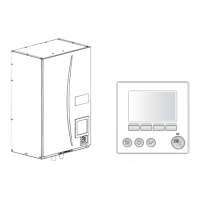
Guide to using the W3000 compact keyboard for unit control.
Instructions for switching the unit on and off using the ON/OFF parameter.
Overview of the controller's menu structure and navigation paths.
How to navigate through the controller's menus and options.
Procedure for accessing the general menu of the controller.
How to select and set the unit's operating mode.
Instructions for adjusting temperature setpoints for different modes.
Information on using KIPlink for unit control via app or remote.
How to turn the unit on/off using the KIPlink interface.
Configuring unit operating mode and setpoints via KIPlink.
Methods for switching the unit on/off via digital input or time bands.
Using digital inputs to remotely switch the unit on or off.
Setting schedules for the unit to turn on and off automatically.
Options for remote monitoring and control of unit operations.
Instructions for connecting remote keyboards to the unit.
Details on installing T-shunts for network connections.
Wiring diagrams for connecting a remote keyboard within 200 meters.
Connection diagrams for remote keyboards over 200 meters, including power units.
Guidance on installing and connecting room thermostats for temperature control.
Description of the Touch Room HMI front panel interface.
Instructions for assembling the Touch Room HMI on the wall.
Steps for flush-mounting the HMI into a wall opening.
Steps for mounting the HMI using a cantilevered bracket.
Wiring guide for connecting the pCOOEM+ controller to the HMI.
Essential safety measures and guidelines for performing maintenance.
Specific precautions for maintenance on units with R32 refrigerant.
Schedule and description of recommended planned maintenance activities.
List of spare parts recommended for replacement over time.
Instructions for cleaning the unit's air heat exchanger coils.
Specific cleaning instructions for treated copper-aluminium coils.
Step-by-step guide for the correct decommissioning and disposal of R32 units.