EasyManua.ls Logo

Mitsubishi Electric MR-C375C-ST-A User Manual

Mitsubishi Electric MR-C375C-ST-A
36 pages
To Next Page IconTo Next Page
Page #1 background imageLoading...
Page #1 background image
Changes for the Better
Models
CONTENTS
A………….......Australia & New Zea land
1. SPECIFICATIONS....................................................
2. OUTLINES AND DIMENSIONS..................................
3. WIRING DIAGRAM....................................................
4. REFRIGERANT CIRCUIT...........................................
5. NAMES OF THE PARTS...........................................
6. TROUBLE SHOOTING..............................................
6.1 TROUBLE CRITERION OF MAIN PARTS.......
6.2 FUNCTION OF OPERATION PANEL..............
6.3 FLOW CHART OF SELF-CHECK....................
6.4 TEST POINT DIAGRAM OF MAIN CONTROL
BOARD........................................................
7. DISASSEMBLY INSTRUCTIONS...............................
8. PARTS LIST............................................................
1
3
5
7
9
11
11
14
15
18
19
24
MR-C375C-W-A
MR-C375C-ST-A
MR-C375C-OB-A
MR-C375CL-W-A
MR-C375CL-ST-A
MR-C405C-W-A
MR-C405C-ST-A
MR-C405CL-W-A
MR-C405CL-ST-A
2012
SERVICE MANUAL
NO
.
SM
-
RE
-
1206
MITSUBISHI
ELECTRIC
HOME REFRIGERATORS
Question and Answer IconNeed help?

Do you have a question about the Mitsubishi Electric MR-C375C-ST-A and is the answer not in the manual?

Mitsubishi Electric MR-C375C-ST-A Specifications

General IconGeneral
BrandMitsubishi Electric
ModelMR-C375C-ST-A
CategoryRefrigerator
Reversible DoorNo
Total Capacity375L
Width600mm
Depth65 cm
Height170 cm

Summary

SPECIFICATIONS

1-1 SPECIFICATIONS

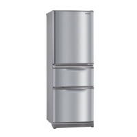
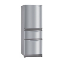
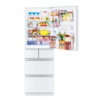
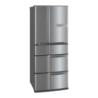
Details the electrical and physical specifications of the refrigerator models.

1-2 ELECTRICAL PARTS SPECIFICATION

Provides detailed electrical specifications for key components like compressor, fans, and heaters.

OUTLINES AND DIMENSIONS

MR-C375C-A/CL-A Dimensions and Installation Space

Presents dimensional drawings and required installation space for specific refrigerator models.

MR-C405C-A/CL-A Dimensions and Installation Space

Presents dimensional drawings and required installation space for specific refrigerator models.

WIRING DIAGRAM

Skeleton Wiring Diagram

Illustrates the basic electrical connections of the refrigerator.

Actual Wiring Diagram

Shows the detailed and actual electrical wiring layout of the refrigerator.

REFRIGERANT CIRCUIT

Refrigerant Flow Diagram

Depicts the path of the refrigerant within the cooling system.

NAMES OF PARTS

Refrigerator Compartment Parts

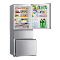
Identifies and labels components within the refrigerator compartment.

Freezer and Automatic Ice-Maker Parts

Identifies and labels components within the freezer compartment and ice maker.

Vegetable Compartment Parts

Identifies and labels components within the vegetable compartment.

TROUBLE SHOOTING

6.1 Trouble Criterion of Main Parts

Outlines the criteria for checking the main components for faults.

Component Checks: Compressor to PTC Relay

Details checks for compressor, run capacitor, motor protector, and PTC relay.

Component Checks: Fan Motor to Motor Damper

Details checks for fan motors, water pump motor, and motor damper.

Component Checks: Heaters and Thermistors

Details checks for heaters and thermistors, including resistance values.

Self-Check Troubleshooting Guidance

Provides guidance on troubleshooting using the refrigerator's self-check feature.

OPERATION PANEL AND SELF-CHECK FUNCTIONS

6.2 Function of Operation Panel

Explains normal operation and the ice making stop LED/switch function.

6.3 Flow Chart of Self-Check Overview

Illustrates the step-by-step process for self-check troubleshooting.

LED Trouble Display and Check Points

Details LED indicators for faults and corresponding check points.

LED Trouble Codes and Corrective Actions

Maps specific LED blink codes to faults and corrective actions.

CONTROL BOARD AND DISASSEMBLY

6.4 Test Point Diagram of Main Control Board

Shows test points and connector assignments for the main control board.

General Disassembly Precautions and PCB Removal

Provides precautions and steps for disassembling PCB components.

Interior Compartment and Panel Disassembly

Guides on removing various interior parts and panels.

Freezer, Ice Maker, and Compressor Component Disassembly

Details disassembly of freezer, ice maker, and compressor components.

Compressor and Dryer Replacement Procedure

Provides detailed instructions for replacing the compressor and dryer.

PARTS LISTS

Door and Body Parts (Identification and List)

Combines identification diagrams and detailed lists for door and body parts.

Electrical Parts (Location Diagram and List)

Combines location diagrams and detailed lists for electrical parts.

Accessory and Unit Parts (Identification and List)

Combines identification diagrams and detailed lists for accessory and unit parts.

Packing Parts (Identification Diagram and List)

Combines identification diagrams and detailed lists for packing parts.

Related product manuals