EasyManua.ls Logo

Mitsubishi Electric MR-C375C-W-A User Manual

Mitsubishi Electric MR-C375C-W-A
36 pages
To Next Page IconTo Next Page
Page #1 background imageLoading...
Page #1 background image
Changes for the Better
Models
CONTENTS
A………….......Australia & New Zea land
1. SPECIFICATIONS....................................................
2. OUTLINES AND DIMENSIONS..................................
3. WIRING DIAGRAM....................................................
4. REFRIGERANT CIRCUIT...........................................
5. NAMES OF THE PARTS...........................................
6. TROUBLE SHOOTING..............................................
6.1 TROUBLE CRITERION OF MAIN PARTS.......
6.2 FUNCTION OF OPERATION PANEL..............
6.3 FLOW CHART OF SELF-CHECK....................
6.4 TEST POINT DIAGRAM OF MAIN CONTROL
BOARD........................................................
7. DISASSEMBLY INSTRUCTIONS...............................
8. PARTS LIST............................................................
1
3
5
7
9
11
11
14
15
18
19
24
MR-C375C-W-A
MR-C375C-ST-A
MR-C375C-OB-A
MR-C375CL-W-A
MR-C375CL-ST-A
MR-C405C-W-A
MR-C405C-ST-A
MR-C405CL-W-A
MR-C405CL-ST-A
2012
SERVICE MANUAL
NO
.
SM
-
RE
-
1206
MITSUBISHI
ELECTRIC
HOME REFRIGERATORS
Question and Answer IconNeed help?

Do you have a question about the Mitsubishi Electric MR-C375C-W-A and is the answer not in the manual?

Mitsubishi Electric MR-C375C-W-A Specifications

General IconGeneral
BrandMitsubishi Electric
ModelMR-C375C-W-A
CategoryRefrigerator
Total Capacity375 L
ColorWhite
Weight65 kg
Number of Doors2
Shelves MaterialTempered Glass
Voltage220-240 V
Frequency50 Hz
TypeTop Mount Freezer

Summary

Specifications Overview

General Model Specifications

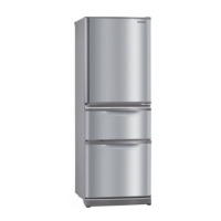
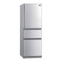
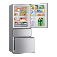
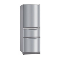
Detailed specifications for MR-C375C-A and MR-C375CL-A models.

Wiring Diagram

Basic Wiring Diagram

Illustrates the fundamental electrical connections and component layout.

Detailed Wiring Diagram

Shows the precise wiring connections and component placement for the unit.

Trouble Shooting

Main Component Troubleshooting

Provides specific checks and criteria for diagnosing major system components.

Self-Diagnostic Flowchart

Guides users through the self-diagnostic process for identifying operational faults.

LED Error Indicators and Checks

Details LED indicators for troubleshooting and corresponding diagnostic steps.

Main Control Board Test Points

Illustrates diagnostic test points on the main control board.

Disassembly Instructions

Control PCB Removal Procedure

Step-by-step guide for safely removing the main control board assembly.

Related product manuals