Do you have a question about the Mitsubishi Electric MR-C405C-ST-A and is the answer not in the manual?
| Brand | Mitsubishi Electric |
|---|---|
| Model | MR-C405C-ST-A |
| Category | Refrigerator |
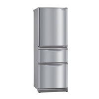
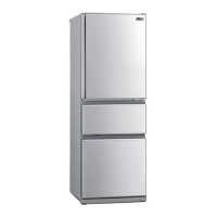
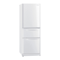
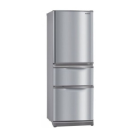
| Color | Stainless Steel |
| Total Capacity | 405 Liters |
| Voltage | 220-240 V |
| Frequency | 50 Hz |
| Energy Efficiency | 4 Stars |
Detailed technical specifications for the refrigerator models, including capacity and dimensions.
Specifications for electrical components, power supply, and ratings of the appliance.
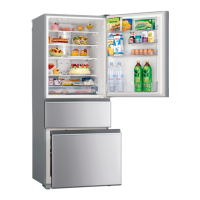
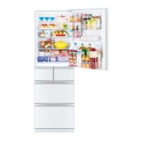
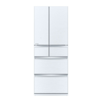
Visual representations and measurements of the refrigerator's exterior and internal layout.
Diagrams illustrating the electrical connections and wiring paths within the unit.
Visual representation of the refrigerant circulation system and its components.
Labeled diagrams identifying all parts within the refrigerator and freezer compartments.
Guidelines for testing and verifying the condition of key internal parts for faults.
Explanation of control panel features for operation and self-diagnosis of the appliance.
A visual guide for performing and interpreting the refrigerator's automatic self-check diagnostic function.
Diagrams indicating specific test points on the main control board for electrical troubleshooting.
Steps for detaching the main control board and associated electrical components.
Instructions for removing the covers for the internal refrigerator lights.
Procedures for detaching components located within the vegetable compartment.
Steps for removing various parts from the primary refrigerator compartment.
Guidance on safely removing the defrost heater and associated drip tray.
Instructions for detaching components from the freezer section.
Detailed steps for disassembling the vegetable compartment door.
Procedures for removing the compressor cover and the compressor unit itself.
Illustrated catalog of parts for the refrigerator's doors and main body.
Visual guide showing the placement of electrical components within the appliance.
Illustrated list of accessories and major unit parts included with the appliance.
Diagrams and list of parts used for securing and protecting the appliance during transit.