EasyManua.ls Logo

Mitsubishi Electric Mr.SLIM PE-5EAK User Manual

Mitsubishi Electric Mr.SLIM PE-5EAK
64 pages
To Next Page IconTo Next Page
Page #1 background imageLoading...
Page #1 background image
TECHNICAL & SERVICE MANUAL
SPLIT-TYPE, AIR CONDITIONERS
CONTENTS
1. PART NAMES AND FUNCTIONS··········2
2. SPECIFICATIONS ··································4
3. DATA·······················································7
4. OUTLINES AND DIMENSIONS ···········16
5. WIRING DIAGRAM·······························20
6.
REFRIGERANT SYSTEM DIAGRAM
········21
7. TROUBLESHOOTING··························23
8. FUNCTION SETTING···························36
9. SYSTEM CONTROL·····························42
10. DISASSEMBLY PROCEDURE·············56
11. RoHS PARTS LIST·······························58
12. OPTIONAL PARTS·······························62
<Indoor unit>
[Model names] [Service Ref.]
PE-3EAK
PE-3EAK.TH
PE-3EAK.TH-U
PE-4EAK
PE-4EAK.TH
PE-4EAK.TH-U
PE-5EAK
PE-5EAK.TH
PE-5EAK.TH-U
PE-6EAK
PE-6EAK.TH
PE-6EAK.TH-U
No. OC394
Indoor unit
Ceiling Concealed
Series PE
ON/OFF
TEMP.
Remote controller
This manual does not cover
outdoor units.
When servicing them, please
refer to the service manual
No. OC152, OC206, OC353
and this manual in a set.
NOTE:
• This service manual describes technical data of indoor units.
• RoHS compliant products have <G> mark on the spec name plate.
May 2006
OC394--1.qxp 06.5.23 5:44 PM Page 1

Table of Contents

Question and Answer IconNeed help?

Do you have a question about the Mitsubishi Electric Mr.SLIM PE-5EAK and is the answer not in the manual?

Mitsubishi Electric Mr.SLIM PE-5EAK Specifications

General IconGeneral
BrandMitsubishi Electric
ModelMr.SLIM PE-5EAK
CategoryAir Conditioner
LanguageEnglish

Summary

PART NAMES AND FUNCTIONS

Indoor (Main) Unit

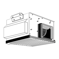
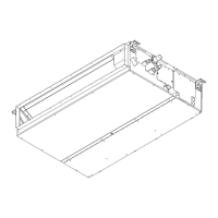
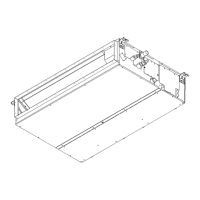
Details of the indoor unit components.

Remote controller

Components and operation of the remote controller.

Display

Display Indicators

Explains various indicators on the remote controller display.

Caution

Important notes regarding operation and indicators.

SPECIFICATIONS

2-1 STANDARD SPECIFICATIONS

Technical specifications for indoor and outdoor units.

POWER SUPPLY & MODEL NAMES

2-2. POWER SUPPLY & MODEL NAMES

Information on power supply types and corresponding model names.

ELECTRICAL SPECIFICATIONS

2-3. ELECTRICAL SPECIFICATIONS

Electrical details like voltage, current, and power for indoor units.

DATA

3-1. PERFORMANCE DATA

Cooling capacity and correction factors for different conditions.

Cooling Capacity Correction Factors

50Hz Factors

Correction factors based on refrigerant piping length at 50Hz.

60Hz Factors

Correction factors based on refrigerant piping length at 60Hz.

STANDARD OPERATION DATA

3-2. STANDARD OPERATION DATA

Operational data like capacity, input, and refrigerant circuit details.

FAN PERFORMANCE AND CORRECTED AIRFLOW

PE-3EAK.TH / PE-3EAK.TH-U

Fan performance curves for PE-3EAK models.

PE-4EAK.TH / PE-4EAK.TH-U

Fan performance curves for PE-4EAK models.

FAN PERFORMANCE AND CORRECTED AIRFLOW

PE-5EAK.TH / PE-5EAK.TH-U

Fan performance curves for PE-5EAK models.

PE-6EAK.TH / PE-6EAK.TH-U

Fan performance curves for PE-6EAK models.

OUTLINES AND DIMENSIONS

4-1. INDOOR UNIT

Dimensional drawings and part identification for indoor units.

REMOTE CONTROLLER DIMENSIONS

4-2. REMOTE CONTROLLER

Dimensional drawing of the remote controller.

WIRING DIAGRAM

5 WIRING DIAGRAM

Wiring diagrams for indoor units and error code interpretations.

REFRIGERANT SYSTEM DIAGRAM

6 REFRIGERANT SYSTEM DIAGRAM

Refrigerant circuit diagrams for different models.

TROUBLESHOOTING

7-1. TROUBLESHOOTING

General troubleshooting guide based on error codes and symptom recurrence.

7-2. MALFUNCTION-DIAGNOSIS METHOD BY REMOTE CONTROLLER

Method to diagnose malfunctions using the wired remote controller.

SELF-DIAGNOSIS ACTION TABLE

7-3. SELF-DIAGNOSIS ACTION TABLE

Detailed troubleshooting steps for specific error codes (P1, P2, P4, P5).

TROUBLESHOOTING BY INFERIOR PHENOMENA

7-4. TROUBLESHOOTING BY INFERIOR PHENOMENA

Troubleshooting for LED status and wiring issues.

TEST RUN AND EMERGENCY OPERATION

7-5. TEST RUN AND EMERGENCY OPERATION

Procedures for test run and emergency operation.

HOW TO CHECK THE PARTS

7-6. HOW TO CHECK THE PARTS

Procedures for checking thermistors and fan motors.

TEST POINT DIAGRAM

7-7. TEST POINT DIAGRAM

Test points on the power board.

Indoor Controller Board Test Points

7-7-2. Indoor controller board

Test points on the indoor controller board.

FUNCTIONS OF DIP SWITCH AND JUMPER WIRE

7-8. FUNCTIONS OF DIP SWITCH AND JUMPER WIRE

Explanation of dip switch and jumper wire functions.

FUNCTION SETTING

8-1. UNIT FUNCTION SETTING BY THE REMOTE CONTROLLER

Settings configurable via the remote controller.

Function Selection Procedure

[Operating Procedure]

Step-by-step guide for function selection.

REMOTE CONTROLLER FUNCTION SELECTION

8-2. FUNCTION SELECTION OF REMOTE CONTROLLER

Detailed explanation of remote controller function settings.

SYSTEM CONTROL

9-1. VARIETY OF SYSTEM CONTROL FUNCTIONS

Overview of different system control configurations.

ONE REMOTE CONTROLLER OPERATION

9-2. ONE REMOTE CONTROLLER (STANDARD) OPERATION

Operation with a single wired or wireless remote controller.

TWO-REMOTE CONTROLLER OPERATION

9-3. TWO-REMOTE CONTROLLER OPERATION

Operation with two wired or wireless remote controllers.

GROUP CONTROL OPERATION

9-4. GROUP CONTROL OPERATION

Collective operation of multiple refrigerant systems.

MA Remote Controller Usage

Use as a Wired Remote Control

Configuration for using MA remote controller.

Interface Unit Settings

SW502: Air Conditioner Function Settings

Settings for functions like heat pump type, auto mode, fan speed.

Test Run Operations

3. Test Run (Check Operations)

Checking interface status via LED lamps.

Interface Unit Mounting

4. Mounting the Remote Control Interface Unit

Instructions for mounting the interface unit.

Power Outage Recovery

9-5. POWER OUTAGE AUTOMATIC RECOVERY OPERATION

How the unit recovers after a power outage.

Separate Room Control

9-6. INDIVIDUAL CONTROL OPERATION FROM A SEPARATE ROOM

Individual control of units from a central room.

Combined Remote/Local Control

9-7. COMBINED REMOTE/LOCAL CONTROL

Control from remote and local locations.

Remote Display Output

9-8. OBTAINING REMOTE DISPLAY

Using adapter for remote display output.

Timer Operations

9-9. TIMER OPERATION

Setting timer operations for units.

Peripheral Equipment Operation

Humidifier Signal

9-11. OBTAINING HUMIDIFIER SIGNAL

Obtaining humidifier signal for heating operation.

External Temperature Sensor

9-12. EXTERNAL MOUNTING OF TEMPERATURE SENSOR

External temperature sensor mounting.

Multiple Remote Control Display

9-13. MULTIPLE REMOTE CONTROL DISPLAY

Controlling units with a multiple remote display.

Duct Fan Interlocking

DISASSEMBLY PROCEDURE

10. DISASSEMBLY PROCEDURE

Steps for disassembling the indoor unit.

RoHS PARTS LIST

11 RoHS PARTS LIST

Structural parts list with RoHS compliance information.

ELECTRICAL PARTS

ELECTRICAL PARTS

List of electrical components with part numbers.

OPTIONAL PARTS

12 OPTIONAL PARTS

List of optional accessories and their part numbers.

Related product manuals