Do you have a question about the Mitsubishi Electric Mr.SLIM PE-6EAK and is the answer not in the manual?
| Series | Mr. Slim |
|---|---|
| Refrigerant | R410A |
| Weight (Indoor Unit) | 9 kg |
| Application | Commercial |
| Power Supply | 220-240V, 50Hz |
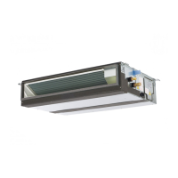
Overview of the Series PE ceiling concealed air conditioners and manual scope.
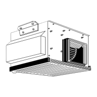
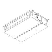
Identification of main parts and components of the indoor unit.
Explanation of the buttons and their functions on the remote controller.
Detailed explanation of various indicators shown on the remote controller display.
Key notes and cautions regarding unit operation and controller messages.
Technical data for PE-3/4EAK indoor units: airflow, noise, dimensions.
Technical data for PE-3/4EAK outdoor units: capacity, motor output, dimensions.
Technical data for PE-5/6EAK indoor units: airflow, noise, dimensions.
Technical data for PE-5/6EAK outdoor units: capacity, motor output, dimensions.
Mapping between service references, model names, and power supply details.
Electrical data for indoor units based on voltage and frequency.
Cooling capacity for PE-3/4EAK at 50Hz under various conditions.
Cooling capacity for PE-5/6EAK at 50Hz under various conditions.
Cooling capacity for PE-3/4EAK at 60Hz under various conditions.
Cooling capacity for PE-5/6EAK at 60Hz under various conditions.
Factors to adjust cooling capacity based on refrigerant pipe length at 50Hz.
Factors to adjust cooling capacity based on refrigerant pipe length at 60Hz.
Electrical, refrigerant, and side specifications for PE-3/4EAK units.
Electrical, refrigerant, and side specifications for PE-5/6EAK units.
Fan performance curves and corrected airflow for PE-3/4EAK models.
Fan performance curves and corrected airflow for PE-5/6EAK models.
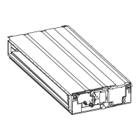
Dimensional drawings and part labels for the PE-3EAK indoor unit.
Dimensional drawings and part labels for the PE-4EAK indoor unit.
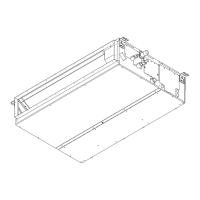
Dimensional drawings and part labels for the PE-5/6EAK indoor units.
Dimensional drawing showing the physical size of the remote controller.
Wiring diagram for indoor units and identification of key components.
List of error codes and their symptoms for troubleshooting.
Refrigerant flow diagram for PE-3EAK with PU-3A/3C outdoor units.
Refrigerant flow diagrams for PE-4/5/6EAK with various outdoor units.
Overview of actions for reoccurring and non-reoccurring phenomena.
Procedure for diagnosing malfunctions using the wired remote controller.
List of error codes detected by the indoor unit and their symptoms.
Notes on operation after test run and LED indicator functions.
Cause and countermeasure for room temperature thermistor abnormality.
Cause and countermeasure for drain sensor and drain pump errors.
Cause and countermeasure for freezing/overheating protection.
Cause and countermeasure for pipe temperature errors.
Cause and countermeasure for remote controller transmission errors.
Cause and countermeasure for indoor/remote controller board errors.
Cause and countermeasure for forced compressor stop due to water leakage.
Cause and countermeasure when LED2 is off.
Cause and countermeasure when LED2 is blinking.
Cause and countermeasure for vane performance issues.
Cause and countermeasure for wireless remote controller receiver issues.
Pre-test run checks for installation and wiring integrity.
Procedure for performing a test run using the wired remote controller.
Procedure for emergency operation when remote controller or unit fails.
Procedure for checking room and coil thermistor resistance values.
Procedure for checking fan motor resistance and relay connector.
Diagram showing test points on the power board.
Diagram identifying connectors and test points on the indoor controller board.
Explanation of functions controlled by SW1 (model) and SW5 (system settings).
Settings for wireless remote controller pair number with J41/J42.
List of functions settable via remote controller and their initial settings.
Availability of functions across different unit types.
Procedure for setting the rotation operation mode.
Step-by-step guide for setting functions using the wired remote controller.
Visual guide for selecting and setting unit functions.
Diagrams showing system configurations for function setting.
Detailed procedure for changing function settings via remote controller.
How to set language and function limits like operation lock.
How to set mode selection (main/sub) and display options.
Detailed flowchart for changing language, function limits, mode, and display settings.
Standard remote control operation of indoor units.
Using two controllers for operation.
Using one remote controller for multiple units.
Combined remote and local control operation.
Operation via external signals.
External signal for display and control.
Enabling timer control for start and stop.
Interlocking with peripheral equipment like Lossnay.
Rotation operation modes.
Wiring and settings for one wired remote controller.
Wiring and settings for wireless remote controller.
Wiring and settings for two wired remote controllers.
Wiring and settings for two wireless remote controllers.
Wiring and settings for one wired and one wireless controller.
How to connect the MA& CONTACT TERMINAL interface.
Connecting the remote control interface with systems.
Important notes and precautions when using the MA remote controller.
Setting refrigerant addresses using SW501.
Detailed configuration of refrigerant addresses 0-15.
Settings for Room Temperature Detector and Mr. SLIM model presence.
SW502 settings for cooling vs. heat pump types.
SW502 settings for auto mode and fan speed.
SW502 settings for vane, swing, and fan mode.
Explanation of LED indicators on the interface unit.
Guidelines for mounting the interface unit directly to a wall.
How the system recovers operation after a power outage.
Controlling units individually from a separate room.
How to combine remote and local control.
Wiring diagrams and examples for combined control.
Wiring for remote display and locally procured parts.
Using an on-site timer for unit operation.
Timer control patterns: independent and combined.
Linked operation with Lossnay units.
Getting humidifier signal for heating operation.
Wiring for multiple remote control display.
Interlocking operation with a duct fan.
Step-by-step guide to remove the drain pan.
Steps to remove electrical components like boards and capacitors.
Procedure to remove the indoor coil thermistor.
Detailed steps for removing the fan assembly and motor.
List of structural parts for PE-3EAK models with RoHS compliance.
List of structural parts for PE-4EAK models with RoHS compliance.
List of structural parts for PE-5/6EAK models with RoHS compliance.
List of electrical components with part numbers and specifications.
Specifications for optional refrigerant piping kits.
Adapter for multiple remote control display.
Adapter for remote ON/OFF control.
Optional remote sensor specifications.
Adapter for remote operation display.
Optional wireless remote controller.
Optional signal receiver unit.
Manufacturer name, head office, and publication details.