EasyManua.ls Logo

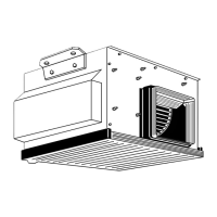
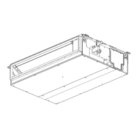
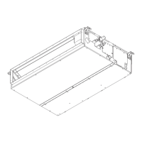
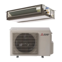
Mitsubishi Electric Mr.SLIM PEH-4EKHSA User Manual

Mitsubishi Electric Mr.SLIM PEH-4EKHSA
60 pages
To Next Page IconTo Next Page
Page #1 background imageLoading...
Page #1 background image
TECHNICAL & SERVICE MANUAL
SPLIT-TYPE, HEAT PUMP AIR CONDITIONERS
CONTENTS
1. FEATURES ···········································2
2. PART NAMES AND FUNCTIONS········3
3. SPECIFICATIONS·································6
4. DATA·····················································8
5. OUTLINES AND DIMENSIONS··········14
6. WIRING DIAGRAM·····························18
7.
REFRIGERANT SYSTEM DIAGRAM
······19
8. OPERATION FLOW-CHART··············20
9. MICROPROCESSOR CONTROL·······24
10. TROUBLESHOOTING························41
11. DISASSEMBLY PROCEDURE···········49
12. PARTS LIST········································51
13. OPTIONAL PARTS ·····························55
Indoor unit
PEH-2.5EKHA
PEH-3EKHA
PEH-4EKHSA
PEH-5EKHSA
No. OC153
[Models]
PEH-2.5EKHA2.TH
PEH-3EKHA
2.TH
PEH-4EKHSA
2.TH
PEH-5EKHSA
2.TH
[Service Ref.]
This manual does not cover the following
outdoor units. When servicing them,
please refer to the service manual
No.OC128,150 and this manual in a set.
[Service Ref.]
PUH-2.5VKA
2
PUH-3VKA2,3YKA2
PUH-4YKSA3
PUH-5YKSA3
PUH-2.5VKA2.UK
PUH-3VKA2.UK
PUH-3YKA
2.UK
PUH-4YKSA2.UK
PUH-5YKSA2.UK
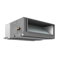
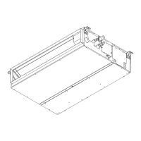
Indoor unit
Ceiling Concealed
Series PEH
The Slim Line.
From Mitsubishi Electric.
FILTER
CHECK MODE
TEST RUN
Remote controller
Question and Answer IconNeed help?

Do you have a question about the Mitsubishi Electric Mr.SLIM PEH-4EKHSA and is the answer not in the manual?

Mitsubishi Electric Mr.SLIM PEH-4EKHSA Specifications

General IconGeneral
BrandMitsubishi Electric
ModelMr.SLIM PEH-4EKHSA
CategoryAir Conditioner
LanguageEnglish

Summary

1 FEATURES

Advanced Microprocessor Capabilities

Details the microprocessor's features: user-friendly remote, LCD display, 24-hr timer, self-diagnosis, and memory.

2 PART NAMES AND FUNCTIONS

3 SPECIFICATIONS

4 DATA

Cooling Capacity Data

Presents cooling capacity and power consumption data based on indoor/outdoor conditions.

10 REMOTE CONTROLLER

11 WIRING DIAGRAM

12 REFRIGERANT SYSTEM DIAGRAM

13 OPERATION FLOW-CHART

14 MICROPROCESSOR CONTROL

15 Indoor Unit Control Logic

Indoor Unit Control: COOL Operation

Details compressor and fan control logic during cooling mode, including time delays and frost prevention.

Indoor Unit Control: DRY Operation

Explains compressor and fan control logic for dry mode, including temperature-dependent operation.

Indoor Unit Control: AUTO Operation

Details the logic for automatic mode selection and changeover based on room and set temperatures.

16 Timer and Test Run Functions

17 Emergency Operation and Temperature Codes

Emergency Operation Mode

Describes how to perform emergency operation by setting dipswitches when controls fail.

19 Dip Switch Functions

Dip Switch Functions Overview

Details DIP switch functions on remote and indoor units for various operational settings.

20 Outdoor Unit Control

21 Defrosting Operation

Defrosting Operation in HEAT Mode

Details the conditions, process, and timing for defrosting operation in heating mode.

23 Service Functions and Time Shortening

Service Functions and Time Shortening

Details compulsory defrosting, fixed fan output, switch functions, and time shortening effects.

24 TROUBLESHOOTING

25 Self-Diagnostic Function

Self-Diagnostic Function

Explains how malfunctions are displayed and how to use the self-diagnostic function for service.

26 Troubleshooting Check Codes

Troubleshooting Check Codes

Provides a table of check codes, their diagnoses, causes, and specific check points for troubleshooting.

27 SERVICE DATA INDICATION

Check Code and Operation Indication

Details how check codes and output states are indicated via LEDs and switches on the outdoor controller.

28 TROUBLESHOOTING BY CHECK CODE

Outdoor Unit Not Working

Lists causes and check points when the outdoor unit fails to operate.

29 Wrong Wiring on Site

Wrong Wiring on Site

Details phenomena resulting from incorrect wiring between units, including check codes.

32 DISASSEMBLY PROCEDURE

34 PARTS LIST

Related product manuals