Do you have a question about the Mitsubishi Electric Mr.SLIM PEH Series and is the answer not in the manual?
| Refrigerant | R410A |
|---|---|
| Series | PEH |
| Type | Heat Pump |
| Indoor Unit Type | Wall-mounted |
| Power Supply | 220-240 V, 50 Hz |
| Operating Temperature (Cooling) | Varies by model |
| Operating Temperature (Heating) | Varies by model |
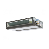
Highlights the unit's ability to be hidden above the ceiling for flexible interior design.
Explains suitability for cooling/heating two rooms simultaneously using air ducts.
Mentions acceptable external static pressure allowing for extensive duct usage.
Details features like user-friendly operation, LCD display, and self-diagnostic capabilities.
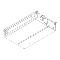
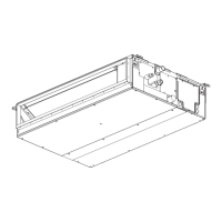
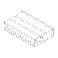
Identifies and illustrates the components of the indoor unit, including air intake and outlets.
Describes the functions of various buttons and displays on the remote controller.
Explains the meaning of different display indicators on the remote controller.
Provides detailed technical specifications for the indoor units.
Lists technical specifications for the outdoor units.
Details specifications related to refrigerant pipe size and connection methods.
Presents cooling capacity data based on varying indoor and outdoor conditions.
Presents heating capacity data based on varying indoor and outdoor conditions.
Shows dimensional drawings and part labels for indoor units.
Lists and defines the symbols used in the wiring diagram.
Shows the detailed wiring connections between indoor and outdoor units.
Illustrates the refrigerant flow for specific indoor/outdoor unit combinations.
Shows the refrigerant system for PEH-4EKHSA2.TH and PUH-4YKSA3(2.UK) units.
Depicts the refrigerant system for PEH-5EKHSA2.TH and PUH-5YKSA3(2.UK) units.
Outlines the primary operation sequence of the air conditioning system.
Details the operational logic and steps for cooling mode.
Illustrates the operational logic and steps for dry mode.
Explains the operational logic and steps for heating mode.
Provides an overview of the microprocessor control system and its inputs/outputs.
Explains the control logic for the indoor unit, including compressor and fan operation.
Details the functions and settings for the timer operation.
Describes how to perform emergency operation and set dipswitches.
Explains the purpose and settings of various dip switches on the controllers.
Describes how the outdoor fan speed is controlled based on coil temperature.
Explains how the outdoor unit turns ON/OFF based on indoor unit commands.
Details various protective functions and their indicators.
Illustrates the timing of operations for compressor, valves, and fan in cooling/heating.
Lists common issues encountered during test runs and their solutions.
Explains how to use the self-diagnostic feature and interpret error codes.
Provides a detailed guide to diagnosing issues based on check codes displayed.
Offers troubleshooting steps for scenarios where the outdoor unit is unresponsive.
Identifies wiring errors and their resulting operational phenomena.
Covers miscellaneous troubleshooting topics and potential causes.
Addresses symptoms that are not malfunctions in the interlock system.
Provides step-by-step instructions for disassembling the indoor unit.
Details the procedure for removing the fan assembly from the indoor unit.
Explains the steps required to remove the heater element.
Lists all structural components of the indoor units with part numbers and quantities.
Lists all electrical components of the indoor units with part numbers and quantities.
Lists optional refrigerant pipe kits and their specifications.
Details specifications and features of the program timer.
Describes the adapter for remote indication and its connection.
Explains the centralized controller for managing multiple units.
Details the adapter needed for program timer or centralized controller use.
Introduces an optional remote controller for managing two controllers.