EasyManua.ls Logo

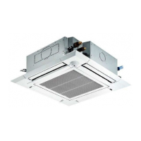
Mitsubishi Electric Mr. Slim PLA-A12EA7 User Manual

Mitsubishi Electric Mr. Slim PLA-A12EA7
44 pages
To Next Page IconTo Next Page
Page #1 background imageLoading...
Page #1 background image
SERVICE MANUAL
CONTENTS
1. REFERENCE MANUAL
........................
2
2. SAFETY PRECAUTION
........................
3
3. PARTS NAMES AND FUNCTIONS
......
5
4. SPECIFICATIONS
...............................
11
5. NOISE CRITERION CURVES
.............
13
6. OUTLINES AND DIMENSIONS
............
15
7. WIRING DIAGRAM
.............................
16
8.
REFRIGERANT SYSTEM DIAGRAM
......
17
9. TROUBLESHOOTING
........................
18
10. FUNCTION SETTING
.........................
32
11. SPECIAL FUNCTION
..........................
33
12. DISASSEMBLY PROCEDURE
...........
37
PARTS CATALOG (OCB640)
WIRED REMOTE
CONTROLLER
(Option)
IR WIRELESS REMOTE
CONTROLLER
(Option)
ON/OFF TEMP
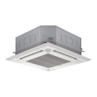
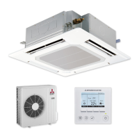
INDOOR UNIT
Model name
indication for
MAIN UNIT
Model name
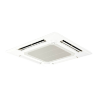
indication for GRILLE
PLA-A12EA7
PLA-A18EA7
PLA-A24EA7
PLA-A30EA7
PLA-A36EA7
PLA-A42EA7
PLA-A12EA7
PLA-A18EA7
PLA-A24EA7
PLA-A30EA7
PLA-A36EA7
PLA-A42EA7
Indoor unit
[Model Name] [Service Ref.]
SPLIT-SYSTEM HEAT PUMP
No. OCH640
REVISED EDITION-C
September 2018
Revision:
• WIRING DIAGRAM has
been modified in REVISED
EDITION-C.
Some descriptions have
been modified.
OCH640 REVISED EDITION-B
is void.
Questions and Answers:

Mitsubishi Electric Mr. Slim PLA-A12EA7 Specifications

General IconGeneral
BrandMitsubishi Electric
ModelMr. Slim PLA-A12EA7
CategoryAir Conditioner
LanguageEnglish

Summary

Reference Manual

Safety Precautions

Always Observe for Safety

General safety warning before accessing terminal, all supply circuits must be disconnected.

Cautions Related to New Refrigerant

Cautions for units utilising refrigerant R410A, including piping and handling.

Cautions for Service

Important precautions for performing service, including refrigerant recovery and filter replacement.

Additional Refrigerant Charge

Procedure for charging refrigerant directly from a cylinder using syphon type.

Service Tools for R410A

List of exclusive service tools required for R410A refrigerant.

Parts Names and Functions

Indoor Unit Components

Diagram and labels identifying components of the indoor unit.

Wired Remote Controller Operation

Explanation of the wired remote controller interface, buttons, and displays.

Remote Controller Display and Menu

Explanation of display modes, icons, menu structure, and settings.

IR Wireless Remote Controller

Diagram and explanation of the IR wireless remote controller buttons and displays.

Specifications

PLA-A12EA7 Specifications

Technical specifications for the PLA-A12EA7 indoor unit, including power, airflow, and noise levels.

PLA-A18EA7 Specifications

Technical specifications for the PLA-A18EA7 indoor unit, including power, airflow, and noise levels.

PLA-A24EA7 Specifications

Technical specifications for the PLA-A24EA7 indoor unit, including power, airflow, and noise levels.

PLA-A30EA7 Specifications

Technical specifications for the PLA-A30EA7 indoor unit, including power, airflow, and noise levels.

PLA-A36EA7 Specifications

Technical specifications for the PLA-A36EA7 indoor unit, including power, airflow, and noise levels.

PLA-A42EA7 Specifications

Technical specifications for the PLA-A42EA7 indoor unit, including power, airflow, and noise levels.

Noise Criterion Curves

PLA-A12EA7 Noise Curves

Noise criterion curves for PLA-A12EA7, showing sound pressure levels across frequency bands.

PLA-A18EA7 Noise Curves

Noise criterion curves for PLA-A18EA7, showing sound pressure levels across frequency bands.

PLA-A24EA7 Noise Curves

Noise criterion curves for PLA-A24EA7, showing sound pressure levels across frequency bands.

PLA-A30EA7 Noise Curves

Noise criterion curves for PLA-A30EA7, showing sound pressure levels across frequency bands.

PLA-A36EA7 Noise Curves

Noise criterion curves for PLA-A36EA7, showing sound pressure levels across frequency bands.

PLA-A42EA7 Noise Curves

Noise criterion curves for PLA-A42EA7, showing sound pressure levels across frequency bands.

Outlines and Dimensions

Indoor Unit Dimensions and Installation

Diagrams illustrating the external dimensions and installation clearances for various indoor unit models.

Wiring Diagram

Indoor Unit Wiring Schematics

Schematic diagrams detailing electrical connections for indoor units and remote controllers.

Refrigerant System Diagram

Refrigerant Flow and Components

Diagram illustrating the refrigerant circuit and flow direction during cooling and heating.

Troubleshooting

General Troubleshooting Overview

Guide for diagnosing and resolving unit issues based on reoccurring or non-reoccurring symptoms.

Malfunction Diagnosis via Remote Controller

Procedure for using the remote controller to diagnose malfunctions and check error codes.

Error Code Tables and LED Indicators

Lists of error codes for indoor/outdoor units, symptoms, remarks, and LED indicator explanations.

Self-Diagnosis Action Table

Table detailing check codes, abnormal points, causes, and countermeasures for unit issues.

Specific Error Code Troubleshooting (P6, P8)

Detailed troubleshooting steps for specific error codes like P6, P8.

Specific Error Code Troubleshooting (P9, PA, E0/E4)

Detailed troubleshooting steps for specific error codes like P9, PA, E0/E4.

Specific Error Code Troubleshooting (E3/E5, E6, E7, Fb)

Detailed troubleshooting steps for error codes E3/E5, E6, E7, Fb.

Specific Error Code Troubleshooting (E1/E2, Pb, PL)

Detailed troubleshooting steps for error codes E1/E2, Pb, PL.

Troubleshooting Inferior Phenomena

Troubleshooting based on specific operational phenomena like vane failure or receiver issues.

Function Setting

Unit Function Settings via Remote Controller

Guide to setting various unit functions using the remote controller.

Special Function

Rotation, Back-up, and Cut-in Functions

Explanation of rotation, back-up, and 2nd stage cut-in functions for multi-unit systems.

Operation of Rotation/Back-up Functions

Outline and system constraints for rotation and back-up functions.

Setting Rotation Functions

Instructions for setting rotation and cut-in functions via the wired remote controller.

Rotation and Back-up Operation Settings

Step-by-step guide to setting rotation and back-up functions via the service menu.

Back-up Heating Function Operation

Explanation of the back-up heater operation and conditions.

Changing Heater ON Delay Time

Procedure for adjusting the heater ON delay time using the wired remote controller.

Disassembly Procedure

Removing Filter and Air Intake Grille

Steps to remove the air intake grille and filter from the indoor unit.

Removing Electrical Box Cover

Steps to remove the electrical box cover after removing the grille and filter.

Removing Thermistor and Controller Board

Procedures for removing the room temperature thermistor and indoor controller board.

Removing Electrical Box, Fan Motor, and Turbo Fan

Steps for removing the electrical box, turbo fan, and fan motor.

Removing Panels and Corner Components

Procedure to remove panels, electrical box cover, corner panel, and grille.

Removing Drain Pan

Steps to remove the electrical box, bell mouth, and drain pan.

Removing Thermistors TH2/TH5

Procedure to remove the drain pan, coil plate, and disconnect thermistors.

Removing Drain Pump and Float Switch

Steps to remove the drain pump and float switch.

Removing Heat Exchanger

Steps to remove the heat exchanger assembly including covers and supports.

Related product manuals