EasyManua.ls Logo

Mitsubishi Electric Mr.Slim PLA-A18EA7 User Manual

Mitsubishi Electric Mr.Slim PLA-A18EA7
44 pages
To Next Page IconTo Next Page
Page #1 background imageLoading...
Page #1 background image
SERVICE MANUAL
CONTENTS
1. REFERENCE MANUAL
........................
2
2. SAFETY PRECAUTION
........................
3
3. PARTS NAMES AND FUNCTIONS
......
5
4. SPECIFICATIONS
...............................
11
5. NOISE CRITERION CURVES
.............
13
6. OUTLINES AND DIMENSIONS
............
15
7. WIRING DIAGRAM
.............................
16
8.
REFRIGERANT SYSTEM DIAGRAM
......
17
9. TROUBLESHOOTING
........................
18
10. FUNCTION SETTING
.........................
32
11. SPECIAL FUNCTION
..........................
33
12. DISASSEMBLY PROCEDURE
...........
37
PARTS CATALOG (OCB640)
WIRED REMOTE
CONTROLLER
(Option)
IR WIRELESS REMOTE
CONTROLLER
(Option)
ON/OFF TEMP
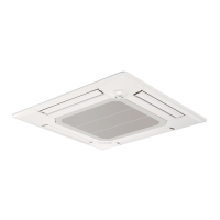
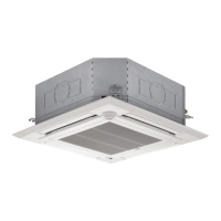
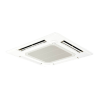
INDOOR UNIT
Model name
indication for
MAIN UNIT
Model name
indication for GRILLE
PLA-A12EA7
PLA-A18EA7
PLA-A24EA7
PLA-A30EA7
PLA-A36EA7
PLA-A42EA7
PLA-A12EA7
PLA-A18EA7
PLA-A24EA7
PLA-A30EA7
PLA-A36EA7
PLA-A42EA7
Indoor unit
[Model Name] [Service Ref.]
SPLIT-SYSTEM HEAT PUMP
No. OCH640
REVISED EDITION-C
September 2018
Revision:
• WIRING DIAGRAM has
been modified in REVISED
EDITION-C.
Some descriptions have
been modified.
OCH640 REVISED EDITION-B
is void.

Questions and Answers:

Mitsubishi Electric Mr.Slim PLA-A18EA7 Specifications

General IconGeneral
BrandMitsubishi Electric
ModelMr.Slim PLA-A18EA7
CategoryAir Conditioner
LanguageEnglish

Summary

SAFETY PRECAUTION

CAUTIONS RELATED TO NEW REFRIGERANT

Specific precautions for handling R410A refrigerant, including pipe preparation and tool usage.

PARTS NAMES AND FUNCTIONS

Wired remote controller (Option)

Details on the controller interface, buttons, and display indicators for wired remote operation.

IR wireless remote controller (Option)

Explanation of the IR remote controller's display, buttons, and operational modes.

SPECIFICATIONS

OUTLINES AND DIMENSIONS

WIRING DIAGRAM

REFRIGERANT SYSTEM DIAGRAM

TROUBLESHOOTING

MALFUNCTION-DIAGNOSIS METHOD BY REMOTE CONTROLLER

Procedure for diagnosing malfunctions using the IR wireless remote controller and check codes.

SELF-DIAGNOSIS ACTION TABLE

Table detailing check codes, causes, and countermeasures for self-diagnosis errors.

TROUBLESHOOTING BY INFERIOR PHENOMENA

Troubleshooting common operational failures and their causes and solutions.

EMERGENCY OPERATION

Instructions for operating the unit in emergency mode when the remote controller is unavailable.

HOW TO CHECK THE PARTS

Guides on how to check specific components like thermistors, motors, and switches.

SPECIAL FUNCTION

ROTATION FUNCTION (AND BACK-UP FUNCTION, 2ND STAGE CUT-IN FUNCTION)

Details on alternating unit operation, back-up function, and second stage cut-in operation.

DISASSEMBLY PROCEDURE

Related product manuals