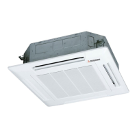
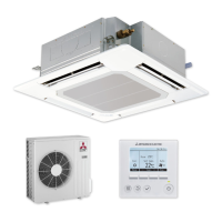
EasyManua.ls Logo

Mitsubishi Electric Mr.SLIM PLP-6EAER1 User Manual

Mitsubishi Electric Mr.SLIM PLP-6EAER1
70 pages
To Next Page IconTo Next Page
Page #1 background imageLoading...
Page #1 background image
SERVICE MANUAL
INDOOR UNIT
PARTS CATALOG (OCB783)
SPLIT-TYPE, HEAT PUMP AIR CONDITIONERS
SPLIT-TYPE, AIR CONDITIONERS
Model name
indication for
MAIN UNIT
Model name
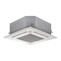
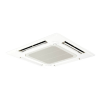
indication for GRILLE
Indoor unit
[Model Name] [Service Ref.]
Grille model
[Model Name] [Service Ref.]
PLP-6EA
PLP-6EAE
PLP-6EAL
PLP-6EALE
PLP-6EAJ
PLP-6EAJE
PLP-6EALM2
PLP-6EALME2
PLP-6EAB
PLP-6EA PLP-6EAR1
PLP-6EAE PLP-6EAER1
PLP-6EAL PLP-6EALR1
PLP-6EALE PLP-6EALER1
PLP-6EAJ
PLP-6EAJE
PLP-6EALM2
PLP-6EALME2
PLP-6EAB
R32/R410A
No. OCH783
REVISED EDITION-B
July 2023
CONTENTS
1. REFERENCE MANUAL ·······················2
2. SAFETY PRECAUTION ·······················2
3. PARTS NAMES AND FUNCTIONS ········8
4. SPECIFICATIONS ······························ 9
5. NOISE CRITERION CURVES ············· 12
6. OUTLINES AND DIMENSIONS ··········· 14
7. WIRING DIAGRAM ··························· 15
8. REFRIGERANT SYSTEM DIAGRAM ··· 16
9. TROUBLESHOOTING ······················· 17
10. FUNCTION SETTING ························ 32
11. SPECIAL FUNCTION ························ 33
12. DISASSEMBLY PROCEDURE ············ 37
13. REMOTE CONTROLLER ··················· 44
PLA-M35EA2
PLA-M35EA2-ER
PLA-M35EA2-ET
PLA-M50EA2
PLA-M50EA2-ER
PLA-M50EA2-ET
PLA-M60EA2
PLA-M60EA2-ER
PLA-M60EA2-ET
PLA-M71EA2
PLA-M71EA2-ER
PLA-M71EA2-ET
PLA-M100EA2
PLA-M100EA2-ER
PLA-M100EA2-ET
PLA-M125EA2
PLA-M125EA2-ER
PLA-M125EA2-ET
PLA-M140EA2
PLA-M140EA2-ER
PLA-M140EA2-ET
PLA-M35EA2.UK
PLA-M35EA2-ER.UK
PLA-M35EA2-ET.UK
PLA-M50EA2.UK
PLA-M50EA2-ER.UK
PLA-M50EA2-ET.UK
PLA-M60EA2.UK
PLA-M60EA2-ER.UK
PLA-M60EA2-ET.UK
PLA-M71EA2.UK
PLA-M71EA2-ER.UK
PLA-M71EA2-ET.UK
PLA-M100EA2.UK
PLA-M100EA2-ER.UK
PLA-M100EA2-ET.UK
PLA-M125EA2.UK
PLA-M125EA2-ER.UK
PLA-M125EA2-ET.UK
PLA-M140EA2.UK
PLA-M140EA2-ER.UK
PLA-M140EA2-ET.UK
Revision:
PLP-6EAB has been added in
REVISED EDITION-B.
OCH783A is
void.

Questions and Answers:

Mitsubishi Electric Mr.SLIM PLP-6EAER1 Specifications

General IconGeneral
BrandMitsubishi Electric
ModelMr.SLIM PLP-6EAER1
CategoryAir Conditioner
LanguageEnglish

Summary

REFERENCE MANUAL

OUTDOOR UNIT'S SERVICE MANUAL

Overview of the outdoor unit's service manual, referencing its contents.

SAFETY PRECAUTION

MEANINGS OF SYMBOLS DISPLAYED ON THE UNIT

Explains the meaning of symbols displayed on the unit for user safety.

ALWAYS OBSERVE FOR SAFETY

Essential safety guidelines to follow before performing any maintenance or work.

CAUTIONS RELATED TO NEW REFRIGERANT

Specific safety precautions for handling new refrigerants like R32/R410A.

[1] Warning for service

[2] Cautions for service

[3] Additional refrigerant charge

[4] Cautions for unit using R32 refrigerant

Servicing and work procedures for R32 units

Detailed servicing steps, safety checks, area precautions, and ignition source control.

Refrigeration equipment and electrical checks

Guidelines for checking refrigeration equipment, electrical devices, and ensuring proper specifications.

Repairs to sealed components and intrinsic safety

Procedures for repairing sealed components and handling intrinsically safe parts correctly.

Flammable refrigerant detection and leak methods

Methods for detecting flammable refrigerants and identifying leaks safely.

Refrigerant removal, evacuation, and charging

Steps for refrigerant removal, system evacuation, charging, and decommissioning.

Refrigerant recovery and decommissioning process

Detailed process for recovering refrigerant, handling cylinders, and decommissioning the unit.

[5] Service tools

Tools for R32/R410A refrigerant systems

List of essential service tools required for working with R32 and R410A refrigerants.

4 SPECIFICATIONS

Indoor unit specifications (PLA-M35EA2, PLA-M50EA2, PLA-M60EA2)

Technical specifications for PLA-M35EA2, PLA-M50EA2, and PLA-M60EA2 indoor units.

Indoor unit specifications (PLA-M71EA2, PLA-M100EA2, PLA-M125EA2)

Technical specifications for PLA-M71EA2, PLA-M100EA2, and PLA-M125EA2 indoor units.

Indoor unit specifications (PLA-M140EA2)

Technical specifications for the PLA-M140EA2 indoor unit.

5 NOISE CRITERION CURVES

Noise levels for PLA-M35EA2 to PLA-M100EA2

Octave band sound pressure levels for models PLA-M35EA2 through PLA-M100EA2.

Noise levels for PLA-M125EA2 and PLA-M140EA2

Octave band sound pressure levels for PLA-M125EA2 and PLA-M140EA2 models.

6 OUTLINES AND DIMENSIONS

Indoor unit installation and dimensional drawings

Diagrams showing installation space, dimensions, and component layout for indoor units.

7 WIRING DIAGRAM

Indoor unit controller board wiring details

Detailed wiring diagram of the indoor controller board, including component connections and legends.

8 REFRIGERANT SYSTEM DIAGRAM

Refrigerant flow path illustration

Diagram illustrating the refrigerant flow in cooling and heating modes, including thermistor locations.

9 TROUBLESHOOTING

Troubleshooting guide based on reoccurring issues

Steps to diagnose and resolve troubles based on whether they are reoccurring or not.

Malfunction diagnosis via remote controller

Instructions for using the remote controller to diagnose malfunctions and check error history.

Indoor unit error codes and symptoms

Table detailing error codes, symptoms, and remarks for indoor unit malfunctions.

Outdoor unit error codes and symptoms

Table detailing error codes, symptoms, and remarks for outdoor unit malfunctions.

Unit operation troubleshooting and LED indications

Troubleshooting for unit operation issues and explanation of indoor controller board LED indicators.

9-3. SELF-DIAGNOSIS ACTION TABLE

Thermistor and drain system error actions

Action table for diagnosing and resolving thermistor and drain system related errors.

Protection and pipe temperature error actions

Action table for freeze/overheat protection and pipe temperature errors.

Pipe temperature and remote controller communication error actions

Action table for pipe temperature (TH5) and remote controller communication errors.

Remote controller communication and compressor stop error actions

Action table for remote controller communication and forced compressor stop errors.

Fan motor and refrigerant circuit error actions

Action table for fan motor trouble and abnormal refrigerant circuit errors.

9-4. TROUBLESHOOTING OF PROBLEMS

LED2 status and refrigerant address troubleshooting

Troubleshooting for LED2 status on the indoor board and refrigerant address setting issues.

LED2 blinking and vane performance troubleshooting

Troubleshooting for LED2 blinking, vane performance, and wireless receiver issues.

9-5. EMERGENCY OPERATION

Emergency operation procedures for controller failure

Steps for activating emergency operation when remote controllers fail or are lost.

9-6. HOW TO CHECK THE PARTS

Checking thermistors, vane motor, and drain components

Methods for checking thermistors, vane motor, drain pump, float switch, and i-see sensor.

Thermistor characteristics and fan motor checks

Thermistor characteristic graph and procedures for checking DC fan motors.

9-7. TEST POINT DIAGRAM

Indoor controller board test point locations

Diagram showing test point locations on the indoor controller board for diagnostics.

9-8. FUNCTIONS OF DIP SWITCH AND JUMPER WIRE

DIP switch and jumper wire function settings

Explanation of DIP switch and jumper wire functions for model and capacity settings.

10 FUNCTION SETTING

Setting unit functions via remote controller

Guide to setting unit functions like filter sign, fan speed, and vane settings via remote.

11 SPECIAL FUNCTION

Automatic filter elevation grille operation

Details on normal and special operations, including re-storage and obstacle detection.

Electrical circuit and wiring for elevation panel

Electrical circuit diagram and wiring for the elevation panel controller board and its components.

11-3. TROUBLESHOOTING

Intake grille operation and noise troubleshooting

Troubleshooting common issues with intake grille operation, positioning, and noise.

11-4. ROTATION FUNCTION & OTHER FUNCTIONS

Rotation, back-up, and 2nd stage cut-in functions

Explanation of rotation, back-up, and 2nd stage cut-in functions in multi-unit systems.

12 DISASSEMBLY PROCEDURE

Filter, air intake grille, and electrical box cover removal

Step-by-step guide to removing the filter, air intake grille, and electrical box cover.

Thermistor and indoor controller board removal

Procedures for removing the room temperature thermistor and the indoor controller board.

Electrical box and turbo fan removal

Steps for removing the main electrical box and the turbo fan assembly.

Fan motor and panel removal

Procedures for removing the fan motor and the corner panel.

Drain pan and thermistor removal

Steps for removing the drain pan and pipe/condenser temperature thermistors.

Drain pump removal procedure

Detailed instructions for safely removing the drain pump unit.

Float switch and heat exchanger removal

Procedures for removing the float switch and the heat exchanger.

13 REMOTE CONTROLLER

PAR-41MAA remote controller functions and buttons

Overview of the PAR-41MAA remote controller's buttons and their primary functions.

Remote controller display modes and icons explained

Explanation of display modes (Full/Basic) and all icons shown on the remote controller.

Remote controller menu structure navigation

Visual map showing how to navigate through the remote controller's menu system.

Remote controller menu options and features

Description of menus for Maintenance, Service, Settings, Check, and Other functions.

Detailed remote controller function settings

In-depth explanation of available function settings like Vane, Timer, Energy Saving, and Restriction.

Remote controller menu operations and settings

Summary of operations and settings within various remote controller menus (Initial, Display, Operation, Maintenance, Service).

PAR-SL97A-E remote controller interface and operation

Explanation of the PAR-SL97A-E remote controller's interface and basic operational guidance.

PAR-SL101A-E remote controller display and functions

Details on the PAR-SL101A-E remote controller display, modes, and functions.

13-2. ERROR INFORMATION

Checking and resetting error status via remote controller

Steps to view error details and reset active errors using the remote controller interface.

Viewing error information from Maintenance menu

How to access and view error information through the Maintenance menu.

13-3. SERVICE MENU

Accessing and navigating the service menu with password

Procedure to access the Service menu, including password entry and navigation.

13-4. TEST RUN

Performing test runs with PAR-41MAA remote controller

Guide for conducting test runs (Cool, Heat, Fan, Vane) using the PAR-41MAA.

Performing test runs with PAR-SL97A-E/PAR-SL101A-E

Test run procedures for PAR-SL97A-E and PAR-SL101A-E remote controllers.

13-5. FUNCTION SETTING

Setting indoor unit functions via PAR-41MAA controller

How to set indoor unit functions like refrigerant address and unit numbers using the PAR-41MAA.

Setting indoor unit functions via PAR-41MAA controller

Continues setting indoor unit functions, covering mode numbers and setting ranges.

Setting functions via PAR-SL97A-E wireless controller

Step-by-step guide for setting functions using the PAR-SL97A-E wireless remote controller.

Setting functions via PAR-SL101A-E wireless controller

Step-by-step guide for setting functions using the PAR-SL101A-E wireless remote controller.

13-6. ROTATION SETTING

Configuring rotation and support functions with PAR-41MAA

How to set rotation periods, backup options, and temperature difference triggers using PAR-41MAA.

13-7. ERROR HISTORY

Viewing and deleting error history records

Instructions for accessing, viewing, and deleting stored error history records.

Viewing and deleting preliminary error history

How to view and clear preliminary error history records from the remote controller.

13-8. SELF-DIAGNOSIS

Performing self-diagnosis and resetting errors with PAR-41MAA

Guide to performing self-diagnosis and resetting error history using the PAR-41MAA remote controller.

Malfunction diagnosis methods for wireless controllers

Procedures for malfunction diagnosis using PAR-SL97A-E and PAR-SL101A-E wireless controllers.

13-9. REMOTE CONTROLLER CHECK

Diagnosing remote controller functionality and issues

Steps to diagnose the remote controller's operation and identify potential faults.

13-10. SMOOTH MAINTENANCE

Setting and viewing smooth maintenance operational data

How to configure smooth maintenance settings and view operational data like run time and temperatures.

13-11. REQUEST CODE

Confirming operation data via request codes

Method to confirm operation data, thermistor temps, and error history using request codes.

Related product manuals