TECHNICAL & SERVICE MANUAL
No.OCH545
SPLIT-TYPE, HEAT PUMP AIR CONDITIONERS
R410A
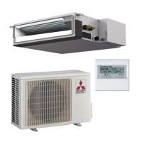
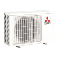
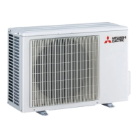
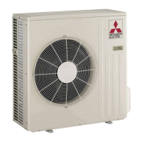
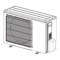
Outdoor unit
[Model Name]
[Service Ref.]
SUZ-KA25VA4 SUZ-KA25VA4.TH
SUZ-KA35VA4 SUZ-KA35VA4.TH
SUZ-KA50VA4 SUZ-KA50VA4.TH
SUZ-KA60VA4 SUZ-KA60VA4.TH
SUZ-KA71VA4 SUZ-KA71VA4.TH
CONTENTS
1.
COMBINATION OF INDOOR AND OUTDOOR UNITS
.....
2
2. TECHNICAL CHANGES
...................................
3
3. PARTS NAMES AND FUNCTIONS
..................
7
4. SPECIFICATION
................................................
8
5. NOISE CRITERIA CURVES
............................
10
6. OUTLINES AND DIMENSIONS
.......................
11
7. WIRING DIAGRAM
..........................................
13
8. REFRIGERANT SYSTEM DIAGRAM
.............
16
9. ACTUATOR CONTROL
...................................
19
10. SERVICE FUNCTIONS
....................................
20
11. TROUBLESHOOTING
.....................................
20
12. DISASSEMBLY INSTRUCTIONS
....................
36
Indication of
model name
Note:
• This service manual
describes technical data of
the outdoor units.
SUZ-KA25VA4.TH
SUZ-KA35VA4.TH
August 2013
PARTS CATALOG (OCB545)