EasyManua.ls Logo

Mitsubishi Electric MS-18NV User Manual

Mitsubishi Electric MS-18NV
32 pages
To Next Page IconTo Next Page
Page #1 background imageLoading...
Page #1 background image
SERVICE MANUAL
SPLIT-TYPE AIR CONDITIONERS
CONTENTS
1. TECHNICAL CHANGES ····································2
2. PART NAMES AND FUNCTIONS······················2
3. SPECIFICATION·················································4
4. OUTLINES AND DIMENSIONS ·························5
5. WIRING DIAGRAM ············································6
6. REFRIGERANT SYSTEM DIAGRAM················7
7. PERFORMANCE CURVES································8
8. MICROPROCESSOR CONTROL ····················10
9. SERVICE FUNCTIONS ····································16
10. TROUBLESHOOTING······································18
11. DISASSEMBLY INSTRUCTIONS·····················24
12. PARTS LIST······················································28
13. OPTIONAL PARTS···········································31
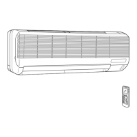
Wireless type
Models
MS-18NV -
(
WH
)
· MU-18NV -
E4E4
No. OB228
MS-18NV -
E4

Questions and Answers:

Mitsubishi Electric MS-18NV Specifications

General IconGeneral
BrandMitsubishi Electric
ModelMS-18NV
CategoryAir Conditioner
LanguageEnglish

Summary

1. TECHNICAL CHANGES

2. PART NAMES AND FUNCTIONS

INDOOR UNIT

Identifies components of the indoor unit for reference.

OUTDOOR UNIT

Identifies components of the outdoor unit for reference.

REMOTE CONTROLLER

Identifies components and buttons of the remote controller.

3. SPECIFICATION

4. OUTLINES AND DIMENSIONS

5. WIRING DIAGRAM

6. REFRIGERANT SYSTEM DIAGRAM

7. PERFORMANCE CURVES

8. MICROPROCESSOR CONTROL

8-1. 'I FEEL CONTROL' OPERATION

Explains the 'I FEEL CONTROL' mode operation and settings.

8-2. COOL OPERATION

Details the procedure and settings for COOL mode operation.

8-3. DRY OPERATION

Details the procedure and settings for DRY mode operation.

8-4. FAN OPERATION

Explains the operation procedure for FAN mode.

8-5. FAN MOTOR CONTROL

Describes the rotational frequency feedback control for fan motors.

8-6. AUTO VANE OPERATION

Explains the auto vane operation and its control.

8-7. SLEEP MODE

Describes the SLEEP mode function and its operation.

8-8. TIMER OPERATION

Explains how to set and use timer functions.

8-9. EMERGENCY-TEST OPERATION

Details the emergency and test operation procedures for servicing.

9. SERVICE FUNCTIONS

9-1. TIMER SHORT MODE

Describes shortening timer settings for service purposes.

9-2. P.C. BOARD MODIFICATION FOR INDIVIDUAL OPERATION

Explains PC board modification for multiple unit operation.

9-3. AUTO RESTART FUNCTION

10. TROUBLESHOOTING

10-1. Cautions on troubleshooting

Provides safety precautions and general checks before troubleshooting.

10-2. Instruction of troubleshooting

Outlines the troubleshooting procedures and flowcharts.

2. Trouble criterion of main parts

A Check of indoor fan motor

B Check of remote controller and receiver P.C. board

C Check of indoor electronic control P.C. board

D Check of outdoor unit

TEST POINT DIAGRAM AND VOLTAGE

11 DISASSEMBLY INSTRUCTIONS

11-1. INDOOR UNIT

Provides instructions for disassembling the indoor unit.

11-2. OUTDOOR UNIT

Provides instructions for disassembling the outdoor unit.

12 PARTS LIST

12-1. INDOOR UNIT STRUCTURAL PARTS

Lists structural parts for the indoor unit.

12-2. INDOOR UNIT HEAT EXCHANGER

Lists parts related to the indoor unit heat exchanger.

12-3. INDOOR UNIT FUNCTIONAL PARTS AND ELECTRICAL PARTS

Lists functional and electrical parts for the indoor unit.

12-4. ACCESSORY PARTS AND REMOTE CONTROLLER

Lists accessory parts and remote controller details.

12-5. OUTDOOR UNIT STRUCTURAL PARTS

Lists structural parts for the outdoor unit.

13 OPTIONAL PARTS

13-1. AIR CLEANING FILTER

Describes the optional air cleaning filter.

13-2. DEODORIZING FILTER

Describes the optional deodorizing filter.

Related product manuals