EasyManua.ls Logo

Mitsubishi Electric MS-18RV-E1 User Manual

Mitsubishi Electric MS-18RV-E1
76 pages
To Next Page IconTo Next Page
Page #1 background imageLoading...
Page #1 background image
SERVICE MANUAL
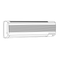
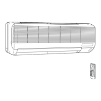
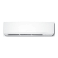
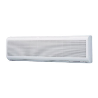
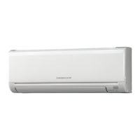
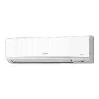
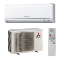
SPLIT-TYPE AIR CONDITIONERS
CONTENTS
1. TECHNICAL CHANGES ····································2
2. PART NAMES AND FUNCTIONS······················3
3. SPECIFICATION·················································6
4. NOISE CRITERIA CURVES·······························8
5. OUTLINES AND DIMENSIONS ·······················10
6. WIRING DIAGRAM ··········································13
7. REFRIGERANT SYSTEM DIAGRAM··············17
8. PERFORMANCE CURVES······························20
9. MICROPROCESSOR CONTROL ····················34
10. SERVICE FUNCTIONS·····································45
11. TROUBLESHOOTING······································47
12. DISASSEMBLY INSTRUCTIONS·····················61
13. PARTS LIST······················································69
14. OPTIONAL PARTS ······················BACK COVER
Wireless type
Models
MS-18RV -
(
WH
)
· MU-18RV -
MS-24RV -
(
WH
)
· MU-24RV -
MS-30RV -
(
WH
)
· MU-30RV -
E1E1
E1E1
E1E1
No. OB271
MS-18RV -
MS-24RV -
E1
E1
OB271--1.qxp 2/7/01 9:00 AM Page 1

Questions and Answers:

Mitsubishi Electric MS-18RV-E1 Specifications

General IconGeneral
BrandMitsubishi Electric
ModelMS-18RV-E1
CategoryAir Conditioner
LanguageEnglish

Summary

Technical Changes

SPECIFICATIONS

OUTLINES AND DIMENSIONS

WIRING DIAGRAMS

MS-18RV Indoor and MU-18RV Outdoor Unit Wiring Diagrams

Illustrates the electrical connections for the MS-18RV indoor and MU-18RV outdoor units.

MS-24RV Indoor and MU-24RV Outdoor Unit Wiring Diagrams

Shows the wiring schematics for the MS-24RV indoor and MU-24RV outdoor units.

MS-30RV Indoor Unit Wiring Diagram

Displays the electrical wiring diagram for the MS-30RV indoor unit.

MU-30RV Outdoor Unit Wiring Diagram

Illustrates the electrical wiring diagram for the MU-30RV outdoor unit.

REFRIGERANT SYSTEM DIAGRAMS

MS-18RV / MU-18RV Refrigerant System Diagram

Details the refrigerant circuit for the MS-18RV indoor and MU-18RV outdoor units.

MS-24RV / MU-24RV Refrigerant System Diagram

Details the refrigerant circuit for the MS-24RV indoor and MU-24RV outdoor units.

MS-30RV / MU-30RV Refrigerant System Diagram

Illustrates the refrigerant circuit for the MS-30RV indoor and MU-30RV outdoor units.

Maximum Refrigerant Piping Length

Additional Refrigerant Charge (R22 : g)

PERFORMANCE CURVES

OUTDOOR LOW PRESSURE AND UNIT CURRENT (COOL OPERATION)

MICROPROCESSOR CONTROL

9-8. Emergency-Test Operation

Describes the procedure for emergency and test operations, including fan speed and mode settings.

9-9. LEV Control (MS-30RV only)

Details the control mechanism and specifications of the LEV (Expansion Valve) for the MS-30RV unit.

SERVICE FUNCTIONS

TROUBLESHOOTING

11-1. Cautions on Troubleshooting

Provides essential safety precautions and checks before commencing troubleshooting procedures.

11-2. Instruction of Troubleshooting

A flowchart guiding the user through troubleshooting steps based on observed symptoms.

Troubleshooting Check Table

A table correlating operation indicator lamp patterns with potential issues and their causes.

Trouble Criterion of Main Parts

Lists main parts with their resistance criteria for diagnosing abnormalities.

A. Check of Indoor Fan Motor

Procedure to diagnose issues with the indoor fan motor when it does not operate.

B. Check of Remote Controller and Receiver P.C. Board

Steps to diagnose problems when the unit does not respond to the remote controller.

C. Check of Indoor Electronic Control P.C. Board

Guides on checking the indoor electronic control P.C. board for faults when the unit is unresponsive.

D. Check of Outdoor Unit

Troubleshooting steps for when the compressor or outdoor fan does not operate.

F. How to Check Mis-wiring (MS-30RV only)

A procedure to identify and resolve mis-wiring issues in the outdoor unit connection.

G. Check of LEV (Expansion Valve)

Diagnostic steps for the LEV (Expansion Valve) when cooling does not operate.

H. Check of Outdoor Thermistor

Procedures to check outdoor thermistors (RT62, RT63) for abnormalities.

TEST POINT DIAGRAM AND VOLTAGE (MS-18RV / MS-24RV Indoor electronic control P.C. board)

MU-30RV Outdoor deicer P.C. board

DISASSEMBLY INSTRUCTIONS

PARTS LIST

13-1. Indoor Unit Structural Parts

Lists structural components of the indoor unit with part numbers and quantities.

Related product manuals