CONTENTS
1. TECHNICAL CHANGES ··································· 2
2. PART NAMES AND FUNCTIONS ····················· 2
3. SPECIFICATION ················································ 3
4. NOISE CRITERIA CURVES ······························ 3
5. OUTLINES AND DIMENSIONS ························ 4
6. WIRING DIAGRAM ············································ 4
7. REFRIGERANT SYSTEM DIAGRAM ··············· 5
8. SERVICE FUNCTIONS ····································· 6
9. MICROPROCESSOR CONTROL ····················· 8
10. TROUBLESHOOTING ····································· 14
11. DISASSEMBLY INSTRUCTIONS ···················· 23
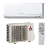
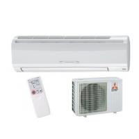
SPLIT-TYPE AIR CONDITIONERS
MS-GD80VB -
E1
SERVICE MANUAL
Wireless type
Model
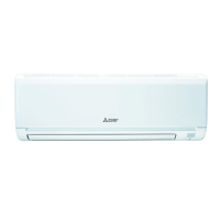
INDOOR UNIT
NOTE:
RoHS compliant products have <G> mark on the spec name plate.
Outdoor unit service manual
MU-GD•VB Series (OBH512)
No. OBH511
REVISED EDITION-A
PARTS CATALOG (OBB511)
Revision A:
• Another type of the electronic control P.C.
board (TYPE 2) has been added to the
original one (TYPE 1). They are both com-
patible with MS-GD80VB-
E1
.
Please void OBH511.