Do you have a question about the Mitsubishi Electric MSC-A07YV-E1 and is the answer not in the manual?
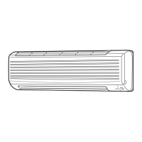
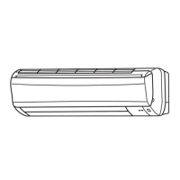
Identifies and describes the various parts of the indoor air conditioner unit.
Lists included accessories for the indoor unit such as installation plates and screws.
Details the components, buttons, and display sections of the wireless remote controller.
Provides technical data including capacity, power, dimensions, and noise levels for indoor units.
Graphs illustrating sound pressure levels across different frequencies and fan speeds.
Presents detailed diagrams showing the physical dimensions and installation points of the indoor unit.
Illustrates the electrical connections and symbol key for the indoor unit.
Shows the refrigerant pipes and the locations of thermistors within the indoor unit.
Explains the remote controller's interface and the meaning of the indoor unit's operation indicator lamp.
Details thermostat control and fan speed adjustments during cooling operation.
Covers coil frost prevention mechanisms and the setup for dry operation mode.
Explains dry mode operation, including set temperature determination and fan speed.
Details compressor/fan cycles, cold air prevention, and fan-only operation.
Describes fan-only mode and heat operation controls, including cold air prevention.
Explains warm air control, the 'I Feel Control' mode, and its operation.
Details initial set temperature decisions, fuzzy control logic, and mode specifics.
Covers fan motor feedback control, lock-up protection, and automatic vane positioning.
Explains Econo Cool mode, swing operations, and how to set timer functions.
Describes how to cancel timers and use the emergency operation switch.
Details setting timer short mode and modifying PC boards for multiple unit operation.
Covers setting the remote controller type and configuring the auto restart function.
Outlines safety precautions, servicing care, and general troubleshooting procedures.
Provides a flowchart to diagnose issues based on the unit's operational status.
A table mapping operation indicator lamp patterns to symptoms and required checks.
Details methods for checking resistance and voltage of key components like thermistors and motors.
Guides on checking the indoor electronic control PC board for faults.
A flowchart to diagnose and resolve issues related to serial signal errors.
Diagrams showing test points, voltages, and component locations on the indoor electronic PC board.
Step-by-step guide for removing the front panel and the indoor electronic control PC board.
Instructions for removing the electrical box, nozzle assembly, vane motor, and fan components.
A list of structural components for the indoor unit with part numbers.
Lists electrical parts and components of the indoor unit heat exchanger.
Details on the air cleaning filter's function, life, and maintenance.
| Brand | Mitsubishi Electric |
|---|---|
| Model | MSC-A07YV-E1 |
| Category | Air Conditioner |
| Language | English |