EasyManua.ls Logo

Mitsubishi Electric MSC-A09WV User Manual

Mitsubishi Electric MSC-A09WV
158 pages
To Next Page IconTo Next Page
Page #1 background imageLoading...
Page #1 background image
SERVICE MANUAL
CONTENTS
1. TECHNICAL CHANGES ····································2
2. PART NAMES AND FUNCTIONS······················6
3. INDOOR/OUTDOOR
CORRESPONDENCE TABLE ···························8
4. INDOOR UNITS COMBINATION ·······················9
5. SPECIFICATION···············································10
6. NOISE CRITERIA CURVES···························· 17
7. OUTLINES AND DIMENSIONS ······················ 20
8. WIRING DIAGRAM ··········································25
9. REFRIGERANT SYSTEM DIAGRAM··············32
10. PERFORMANCE CURVES······························45
11. MICROPROCESSOR CONTROL·····················84
12. SERVICE FUNCTIONS···································102
13. TROUBLESHOOTING····································104
14. DISASSEMBLY INSTRUCTIONS···················129
15. PARTS LIST····················································144
16. OPTIONAL PARTS·········································157
Wireless type
Models
MSC-A07WV -
(
WH
)
· MU-A07WV -
MSC-A09WV -
(
WH
)
· MU-A09WV -
MSC-A12WV -
(
WH
)
· MU-A12WV -
MSC-A07WV -
(
WH
)
· MUH-A07WV -
MSC-A09WV -
(
WH
)
· MUH-A09WV -
MSC-A12WV -
(
WH
)
· MUH-A12WV -
Multi system type
Models
MSC-A07WV -
(
WH
)
· MUX-A10WV -
MSC-A09WV -
(
WH
)
· MUX-A19WV -
MSC-A12WV -
(
WH
)
· MUX-A20WV -
· MUX-A25WV -
· MUX-A26WV -
Inverter-controlled multi system Model
· MXZ-A18WV -
E1
E1
E1
E1E1
E1E1
E1E1
E1E1
E1E1
E1E1
E1E1
E1E1
E1E1
MSC-A07WV -
MSC-A09WV -
MSC-A12WV -
E1
E1
E1
No. OB307
REVISED EDITION-A
HFC
utilized
R410A
SPLIT-TYPE, AIR CONDITIONERS
SPLIT-TYPE, HEAT PUMP AIR CONDITIONERS
Revision:
MXZ-A18WV - have been added.
MSC-A07/09/12WV - Part No.
.
have changed.
VARISTOR (NR11& NR12)
E02 336 385 E02 749 385
Please void OB307.
E1
E1
Indication of
model name
Remote
controller
OB307A1.qxp 03.2.19 3:56 PM Page 1
All manuals and user guides at all-guides.com
all-guides.com
Question and Answer IconNeed help?

Do you have a question about the Mitsubishi Electric MSC-A09WV and is the answer not in the manual?

Mitsubishi Electric MSC-A09WV Specifications

General IconGeneral
BrandMitsubishi Electric
ModelMSC-A09WV
CategoryAir Conditioner
LanguageEnglish

Summary

Technical Changes

Part Names and Functions

INDOOR UNIT

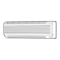
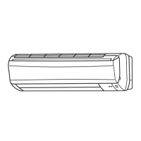
Details the components and functions of the indoor unit.

OUTDOOR UNIT

Details the components and functions of the outdoor unit.

ACCESSORIES

Lists and illustrates the accessories provided with the unit.

REMOTE CONTROLLER

Explains the functions and layout of the wireless remote controller.

Indoor/ Outdoor Correspondence Table

Indoor Units Combination

Specification

Noise Criteria Curves

MSC-A07WV- E1

Noise criteria curves for MSC-A07WV-E1 model, showing sound pressure levels by frequency.

MSC-A09WV- E1

Noise criteria curves for MSC-A09WV-E1 model, showing sound pressure levels by frequency.

MSC-A12WV- E1

Noise criteria curves for MSC-A12WV-E1 model, showing sound pressure levels by frequency.

MU-A07WV- E1

Noise criteria curves for MU-A07WV-E1 model, showing sound pressure levels by frequency.

MU-A09WV- E1

Noise criteria curves for MU-A09WV-E1 model, showing sound pressure levels by frequency.

MUH-A07WV- E1

Noise criteria curves for MUH-A07WV-E1 model, showing sound pressure levels by frequency.

MUH-A09WV- E1

Noise criteria curves for MUH-A09WV-E1 model, showing sound pressure levels by frequency.

MUH-A12WV- E1

Noise criteria curves for MUH-A12WV-E1 model, showing sound pressure levels by frequency.

MUX-A10WV- E1

Noise criteria curves for MUX-A10WV-E1 model, showing sound pressure levels by frequency.

MUX-A19WV - E1

Noise criteria curves for MUX-A19WV-E1 model, showing sound pressure levels by frequency.

MUX-A20WV - E1

Noise criteria curves for MUX-A20WV-E1 model, showing sound pressure levels by frequency.

MUX-A25WV - E1

Noise criteria curves for MUX-A25WV-E1 model, showing sound pressure levels by frequency.

MUX-A26WV - E1

Noise criteria curves for MUX-A26WV-E1 model, showing sound pressure levels by frequency.

MXZ-A18WV - E1

Noise criteria curves for MXZ-A18WV-E1 model, showing sound pressure levels by frequency.

Outlines and Dimensions

INDOOR UNIT

Provides diagrams and dimensions for indoor units MSC-A07/09/12WV.

OUTDOOR UNIT

Provides diagrams and dimensions for MU-A07/09/12WV outdoor units.

REQUIRED SPACE

Specifies the necessary clearance around the outdoor unit for proper installation and airflow.

Wiring Diagram

INDOOR UNIT

Shows the electrical wiring diagram for the indoor unit.

OUTDOOR UNIT

Shows wiring diagrams for MUH/MUX outdoor units.

MXZ-A18WV - E1

Wiring diagram for MXZ-A18WV outdoor unit.

Refrigerant System Diagram

INDOOR UNIT

Illustrates the refrigerant system for MSC/MU series indoor units.

OUTDOOR UNIT

Illustrates the refrigerant system for MU series outdoor units.

MAX. REFRIGERANT PIPING LENGTH

MAX. HEIGHT DIFFERENCE

Specifies maximum allowable height difference between indoor and outdoor units.

ADDITIONAL REFRIGERANT CHARGE(R410A : g)

Details the amount of R410A refrigerant to add based on piping length.

MAX. REFRIGERANT PIPING LENGTH & MAX. HEIGHT DIFFERENCE

ADDITIONAL REFRIGERANT CHARGE (R410A:g)

Specifies additional refrigerant charge required based on piping length for MUX-A10WV.

PIPING PREPARATION

Outlines specifications for pipes and insulation materials used in refrigerant piping.

PERFORMANCE CURVES

How to measure the indoor air wet-bulb/dry-bulb temperature difference

Step-by-step guide to measuring indoor air temperature differences for performance analysis.

OUTDOOR LOW PRESSURE AND OUTDOOR UNIT CURRENT

COOL operation

Presents performance data for COOL operation based on ambient conditions.

HEAT operation

Presents performance data for HEAT operation based on ambient conditions.

CAPACITY AND THE INPUT CURVES (ONE INDOOR UNIT WITH ONE OUTDOOR UNIT)

COOL operation

Shows capacity and input curves for COOL operation with single indoor units.

OUTDOOR LOW PRESSURE AND OUTDOOR UNIT CURRENT

COOL operation

Presents performance data for COOL operation based on ambient conditions.

CAPACITY AND THE INPUT CURVES

MUX-A20WV- E1

Shows capacity and input curves for MUX-A20WV-E1 in single operation.

MUX-A25WV- E1

Shows capacity and input curves for MUX-A25WV-E1 in single operation.

MUX-A26WV- E1

Shows capacity and input curves for MUX-A26WV-E1 in single operation.

Capacity and input correction by inverter output frequency (OUTDOOR UNIT : MXZ-A18WV)

07-class unit in single operation

Details capacity and input corrections based on inverter frequency for 07-class units.

09-class unit in single operation

Details capacity and input corrections based on inverter frequency for 09-class units.

12-class unit in single operation

Details capacity and input corrections based on inverter frequency for 12-class units.

Outdoor low pressure and outdoor unit current 1. 07-class unit in single operation (OUTDOOR UNIT : MXZ-A18WV)

(1) COOL operation

Presents outdoor low pressure and current data for COOL operation of 07-class units.

(2) HEAT operation

Presents outdoor low pressure and current data for HEAT operation of 07-class units.

MICROPROCESSOR CONTROL

WIRELESS REMOTE CONTROLLER

Details the components and functions of the wireless remote controller.

INDOOR UNIT DISPLAY SECTION

Explains the operation indicator lamp and its meaning on the indoor unit.

11-1. COOL ( ) OPERATION

Outlines the procedure and settings for COOL operation mode.

11-2. DRY ( ) OPERATION

11-3. FAN ( ) OPERATION

Details the procedure for FAN operation mode, with only the indoor fan active.

11-4. HEAT ( ) OPERATION

Outlines the procedure and settings for HEAT operation mode.

11-4. HEAT ( ) OPERATION (continued)

3. High pressure protection <MUH-A07/A09/A12WV>

Protection mechanism to prevent compressor discharge pressure rise during heating.

4. Defrosting <MUH-A07/A09/A12WV>

5. R.V. coil control <MUH-A07/A09/A12WV>

11-5. “I FEEL CONTROL” ( ) OPERATION

Details the "I FEEL CONTROL" mode, including temperature settings and fuzzy logic.

11-6. FAN MOTOR CONTROL

11-7. AUTO VANE OPERATION

Describes the automatic vane operation for optimal air distribution in different modes.

11-7. AUTO VANE OPERATION (continued)

(8) ECONO COOL ( ) operation

Explains the ECONO COOL mode for energy saving and comfort.

11-8. TIMER OPERATION

Instructions on how to set and cancel timer operations.

11-9. EMERGENCY-TEST OPERATION

11-10. OUTDOOR UNIT ACTUATOR CONTROL

11-11 INVERTER MULTI SYSTEM CONTROL

MXZ-A18WV - E1

Control system overview for the MXZ-A18WV multi-system inverter air conditioner.

11-11-2. Outline of main power supply circuit

11-11-3. Function of main parts

11-12. Optimal voltage control

Explains how optimal voltage control enhances compressor efficiency and performance.

11-13 LEV control

11-14.Operational frequency range

11-15.Heat defrosting control

Explains the conditions and process for initiating and completing heat defrosting.

11-16.Discharge temperature protection control

11-17.Refrigerant recovery control on heating

Explains refrigerant recovery procedures specifically for heating operations.

11-18.Outdoor fan control

Describes how outdoor fan speed is adjusted based on compressor frequency and indoor unit operation.

11-19.Relation between main sensor and actuator

Illustrates the relationship between various sensors and actuators for system control.

SERVICE FUNCTIONS

12-1. COMPULSORY DEFROSTING MODE FOR SERVICE <MUH-A07/A09/A12WV>

Procedure for forcing defrost mode for service purposes, overriding normal conditions.

12-2. CHANGE IN DEFROST SETTING <MUH-A07/A09/A12WV>

Instructions on how to modify defrost interval time and start temperature.

12-3. TIMER SHORT MODE

Explains how to shorten timer settings for service purposes.

12-4. P.C. BOARD MODIFICATION FOR INDIVIDUAL OPERATION

Guides on modifying P.C. boards for individual indoor unit operation with wireless controllers.

12-5. REMOTE CONTROLLER (How to set the type)

12-6. MU & MUXTYPE/MUH & MXZ TYPE SWITCH OVER AND AUTO RESTART FUNCTION

Details how to switch between MU/MUX and MUH/MXZ types and enable auto restart.

TROUBLESHOOTING

13-1. Cautions on troubleshooting

Important safety precautions and checks to perform before troubleshooting the unit.

3. Troubleshooting procedure

Step-by-step guide to diagnose and resolve common operational issues.

4. How to replace batteries

Instructions for replacing remote controller batteries to resolve malfunctions.

Troubleshooting check table

Self check table

A table listing symptoms, detection methods, and check points for self-diagnosis of abnormalities.

B Check of remote controller and receiver P.C. board

A Check of indoor fan motor

Diagnostic procedure for issues related to the indoor fan motor not operating.

C Check of indoor electronic control P.C. board

D Check of outdoor unit

Troubleshooting steps for issues where the compressor or outdoor fan motor does not operate.

E Check of outdoor unit

F Check of R.V. coil

G How to check mis-wiring and serial signal error

H Check of outdoor thermistor

I Check of indoor/outdoor units’ connection and outdoor unit

Troubleshooting steps for issues where cool air is not blown despite indoor unit operation.

J Check of power supply

K Check of outdoor unit serial signal

Steps to diagnose serial signal communication issues affecting the outdoor unit.

L Check of R. V. coil

M Check of LEV

N Check of inverter/ compressor

Steps to check the inverter and compressor for faults, including voltage and resistance checks.

O Check of outdoor unit thermistor

P Check of outdoor fan motor

Diagnostic steps for issues with the outdoor fan motor not operating or stopping intermittently.

Q The other cases

DISASSEMBLY INSTRUCTIONS

14-1. MSC-A07WV - MSC-A09WV - MSC-A12WV - INDOOR UNIT

Step-by-step guide for disassembling the indoor unit, including panel and P.C. board removal.

14-2. MU-A07WV - MU-A09WV - MU-A12WV - OUTDOOR UNIT

14-3. MUH-A07WV - MUH-A09WV - MUH-A12WV - OUTDOOR UNIT

14-4. MUX-A10WV - OUTDOOR UNIT

14-5. MUX-A19WV - MUX-A20WV - MUX-A25WV - MUX-A26WV - OUTDOOR UNIT

MXZ-A18WV - OUTDOOR UNIT

PARTS LIST

15-1. INDOOR UNIT STRUCTURAL PARTS

Lists structural parts for MSC-A07/09/12WV indoor units.

15-2. ACCESSORY AND REMOTE CONTROLLER

Lists accessories and remote controller parts.

15-3. INDOOR UNIT ELECTRICAL PARTS AND FUNCTIONAL PARTS

15-4. INDOOR UNIT HEAT EXCHANGER

Lists parts related to the indoor unit heat exchanger.

15-5. OUTDOOR UNIT STRUCTURAL PARTS

15-6. OUTDOOR UNIT ELECTRICAL PARTS AND FUNCTIONAL PARTS

15-8. OUTDOOR UNIT ELECTRICAL PARTS AND FUNCTIONAL PARTS

Lists electrical parts and functional components for MUH outdoor units.

15-9. ACCESSORY

Lists accessory items.

15-7. OUTDOOR UNIT STRUCTURAL PARTS

15-8. OUTDOOR UNIT ELECTRICAL PARTS AND FUNCTIONAL PARTS

15-9. ACCESSORY

Lists accessory items.

15-10. OUTDOOR UNIT STRUCTURAL PARTS

15-11. OUTDOOR UNIT ELECTRICAL PARTS AND FUNCTIONAL PARTS

15-12. OUTDOOR UNIT STRUCTURAL PARTS

15-13. OUTDOOR UNIT FUNCTIONAL PARTS AND ELECTRICAL PARTS

15-14. OUTDOOR UNIT FUNCTIONAL PARTS AND ELECTRICAL PARTS

15-15. ACCESSORY

Lists accessory items.

15-16. OUTDOOR UNIT FUNCTIONAL PARTS AND STRUCTURAL PARTS

OPTIONAL PARTS

15-17. AIR CLEANING FILTER

Information on the air cleaning filter, its maintenance, and replacement.

15-18. DEODORIZING FILTER

Information on the deodorizing filter, its cleaning, and replacement.

16-1. Different-diameter pipe

Details specifications for different-diameter pipes used for connecting units.

Related product manuals