Do you have a question about the Mitsubishi Electric MSZ-FD25VA and is the answer not in the manual?
Lists included accessories such as installation plates, screws, and remote controller holder.
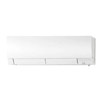
Details electrical data, dimensions, performance ratings, and main electric part specifications.
Shortens set time for service operations via short-circuiting specific points on the P.C. board.
Modifies indoor unit P.C. boards for individual operation of multiple units with wireless remotes.
Restores operation to previous settings after power interruption.
Adjusts slide switch in remote for correct indoor unit installation position and air direction.
Details buttons and functions of the wireless remote controller.
Explains the meaning of the indicator lamps on the indoor unit for operation status.
Describes COOL, DRY modes, coil frost prevention, and low outside temperature operation.
Details HEAT mode, cold air prevention, high pressure protection, and defrosting.
Controls horizontal vane movement for optimal air distribution in various modes.
Uses i-see sensor to measure temperatures for automatic comfort adjustment.
Activates plasma deodorizing and air purifying features.
Sets ON and OFF timers for automatic unit operation.
Allows unit operation via emergency switch for service or when remote is unavailable.
Provides safety precautions and checks before performing troubleshooting.
Instructions on replacing remote controller batteries and resetting the unit.
Guidance on correctly installing the horizontal vane to prevent indicator lamp blinking.
Recalls and displays past abnormal conditions for diagnosis.
Recalls failure modes specific to the plasma operation.
Table correlating POWER lamp blinking patterns to indoor unit abnormalities.
Table correlating POWER lamp blinking patterns to plasma operation abnormalities.
Flowchart guiding diagnosis based on operation status and indicator lamps.
Comprehensive table of symptoms, conditions, and correspondence for troubleshooting.
Checks methods and criteria for diagnosing main component failures.
Step-by-step troubleshooting for indoor fan motor errors.
Diagnoses issues with the remote controller and indoor electronic control P.C. board.
Checks indoor PC board and fan motor for faults.
Guides checking for miswiring and serial signal communication errors.
Specific check for plasma operation issues.
Provides diagrams and voltage values for testing components on the P.C. board.
Details the power monitor receiver P.C. board.
Details the monitor P.C. board.
Details the plasma power P.C. board.
Step-by-step guide to remove the front panel and its components.
Instructions to remove P.C. boards, sensor, and terminal block.
Procedure for removing the electrical box.
Instructions for removing the vertical vane motor unit.
Steps to remove the horizontal vane motor unit.
Guide to remove the indoor fan motor and the line flow fan.
| Cooling Capacity | 2.5 kW |
|---|---|
| Heating Capacity | 3.2 kW |
| Power Supply | 220-240 V, 50 Hz |
| Refrigerant | R410A |
| Indoor Unit Weight | 10 kg |
| Type | Wall Mounted |
| Indoor Unit Dimensions (W x H x D) | 798 x 295 x 257 mm |
| Outdoor Unit Dimensions (W x H x D) | 780 x 550 x 290 mm |