Do you have a question about the Mitsubishi Electric MSZ-HJ25VA-E1 and is the answer not in the manual?
Steps to prepare for air conditioner repair work.
Safety measures to follow while performing air conditioner repair.
Details the addition of a new model to the product line.
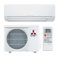
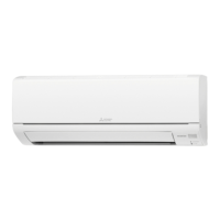
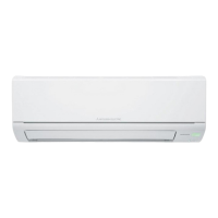
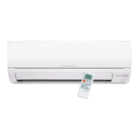
Identifies key components and accessories of the indoor unit.
Provides detailed technical specifications for different models.
Graphs showing sound pressure levels across frequencies for various operating conditions.
Outlines physical measurements and piping connection requirements.
Visual representation of electrical connections and component labels.
Illustrates refrigerant flow paths in cooling and heating modes for different models.
Description of how to shorten the timer delay for service purposes.
Procedure for modifying PC boards for multiple remote controllers.
Explanation of the automatic restart feature and how to disable it.
Overview of buttons, signals, and operation states for the remote controller.
Explains the meaning of the operation indicator lamp's status.
Steps and features for operating in cool mode, including frost prevention.
Steps and features for operating in dry mode.
Steps and features for operating in heat mode, including cold air prevention.
Explains horizontal vane control for different operating modes.
Instructions for setting and releasing ON/OFF timers.
Guidelines for using the emergency switch for testing and operation.
Explanation of the compressor's 3-minute restart delay function.
Important safety and procedural notes before starting diagnosis.
General steps for diagnosing unit abnormalities using indicator lamps.
Guide on replacing batteries to resolve remote controller malfunctions.
Instructions on how to recall and interpret stored failure codes.
Correlates indicator lamp patterns to specific indoor unit faults and remedies.
Guidance on using flowcharts to diagnose unit issues systematically.
Lists abnormal points, symptoms, conditions, and remedies for unit failures.
Methods and criteria for checking the functionality of key internal components.
Step-by-step guide to diagnose and resolve indoor fan motor issues.
Diagnostic steps for issues related to the remote controller and indoor electronic PC board.
Diagnostic steps for issues involving the indoor PC board and fan motor.
Procedures to check for and resolve miswiring or serial signal communication errors.
Steps to mitigate electromagnetic interference with TVs and radios.
Checks to perform before contacting service for noise issues.
Diagrams showing test points and voltage references on the indoor power PC board.
Diagrams showing test points and voltage references on the indoor electronic control PC board.
Guide on how to detach terminals with locking mechanisms.
Step-by-step instructions for removing the indoor unit's front panel.
Procedure for safely removing the indoor power PC board and associated electrical box.
Steps for removing the indoor electronic control PC board.
Instructions for disassembling and removing the vane motor unit.
Detailed steps for removing the indoor fan motor, coil thermistor, and line flow fan.
Procedures for correctly mounting and securing the indoor coil thermistor.
| Brand | Mitsubishi Electric |
|---|---|
| Model | MSZ-HJ25VA-E1 |
| Category | Air Conditioner |
| Language | English |