EasyManua.ls Logo

Mitsubishi Electric MU-GA80VB - User Manual

Mitsubishi Electric MU-GA80VB
40 pages
Print Icon
To Next Page IconTo Next Page
Loading...
SERVICE MANUAL
CONTENTS
1. TECHNICAL CHANGES ····································2
2. PART NAMES AND FUNCTIONS······················5
3. SPECIFICATION·················································6
4. NOISE CRITERIA CURVES·······························8
5. OUTLINES AND DIMENSIONS ·························9
6. WIRING DIAGRAM ··········································10
7. REFRIGERANT SYSTEM DIAGRAM··············12
8. PERFORMANCE CURVES······························15
9. TROUBLESHOOTING······································23
10. DISASSEMBLY INSTRUCTIONS·····················30
11. PARTS LIST······················································36
Wireless type
Models
MU-GA50VB -
MU-GA60VB -
MU-GA80VB -
E1
E1
E1
SPLIT-TYPE, AIR CONDITIONERS
MU-GA50VB -
E1
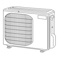
Indication of model name
NOTE:
•This service manual describes technical data of outdoor units.
As for indoor units MS-GA50VB - , MS-GA60VB - and MS-GA80VB - , refer to the service
manual OB369.
E1E1E1
No. OB370
HFC
utilized
R410A
OB370-1.qxp 04.10.14 1:45 PM Page 1

Questions and Answers

  • M
    Mr. James Hendricks PhDAug 2, 2025
    What to do if the OPERATION INDICATOR lamp on my Mitsubishi Electric Air Conditioner is flashing?
    • D
      dgarciaAug 2, 2025
      If the OPERATION INDICATOR lamp on your Mitsubishi Electric Air Conditioner's indoor unit is flashing, it could indicate several issues: * Trouble with the room temperature or indoor coil thermistor: Check the thermistors. * Trouble with the indoor fan motor: Refer to the mentioned check. * Trouble with the indoor unit control system: Replace the indoor electronic control P.C. board. * Trouble with a thermistor in the outdoor unit: Refer to the mentioned check. * Trouble with the outdoor control system: Replace the deicer P.C. board. * Trouble with low discharge temperature protection: Refer to the mentioned check.

Summary

Technical Changes

R410 A Refrigerant Information

Details regarding the R410A refrigerant, its properties, and handling for air conditioners.

Outdoor Unit Part Names and Functions

Outdoor Unit Components

Identification and description of various parts of the outdoor unit for different models.

Unit Specifications

MU-GA50 VB;GA60 VB Specifications

Detailed technical specifications for MU-GA50VB and MU-GA60VB outdoor units.

MU-GA80 VB Specifications

Detailed technical specifications for the MU-GA80VB outdoor unit.

Noise Criteria Curves

Noise Criteria Curves

Sound pressure level curves for MU-GA50VB, MU-GA60VB, and MU-GA80VB models.

Outlines and Dimensions

Outlines and Dimensions

Physical dimensions and required installation space for all models.

Electrical Wiring Diagrams

MU-GA50 VB;GA60 VB Wiring Diagrams

Electrical wiring diagrams for MU-GA50VB and MU-GA60VB outdoor units.

MU-GA80 VB Wiring Diagram

Electrical wiring diagram for the MU-GA80VB outdoor unit.

Refrigerant System and Piping

Refrigerant System Diagrams

Schematics of the refrigerant system for MU-GA50VB and MU-GA60VB.

MU-GA80 VB Refrigerant System Diagram

Schematic of the refrigerant system for the MU-GA80VB model.

Refrigerant Piping and Height Guidelines

Guidelines for maximum refrigerant piping length and height difference.

Additional Refrigerant Charge Calculation

Table detailing additional refrigerant charge based on piping length.

Performance Characteristics

Cooling Performance Curves

Graphs showing cooling capacity and input based on temperatures.

Operating Condition Curves

Charts showing outdoor low pressure and unit current vs. ambient conditions.

MU-GA50 VB Performance Data Tables

Detailed performance data tables for MU-GA50VB cooling operation.

MU-GA60 VB Performance Data Tables

Detailed performance data tables for MU-GA60VB cooling operation.

MU-GA80 VB Performance Data Tables

Detailed performance data tables for MU-GA80VB cooling operation.

Troubleshooting Guide

Troubleshooting Precautions

Important safety and procedural notes before performing troubleshooting.

Troubleshooting Procedures & Flowcharts

Step-by-step guides for diagnosing operational issues.

Main Component Trouble Criteria

Resistance and condition checks for key components.

Compressor & Fan Motor Troubleshooting

Flowchart for compressor and outdoor fan motor operational faults.

Outdoor Unit Operation Troubleshooting

Flowchart for outdoor unit non-operation and indicator lamp issues.

LEV and Thermistor Troubleshooting

Procedures for checking the Expansion Valve (LEV) and thermistors.

Deicer P.C. Board Test Points & Voltages

Diagram of the deicer P.C. board with test points and voltage references.

Disassembly Instructions

MU-GA50 VB Disassembly Instructions

Steps for disassembling the MU-GA50VB outdoor unit.

MU-GA60 VB Disassembly Instructions

Steps for disassembling the MU-GA60VB outdoor unit.

MU-GA80 VB Disassembly Instructions

Steps for disassembling the MU-GA80VB outdoor unit.

Parts List

MU-GA50 VB;GA60 VB Parts List

List of structural, electrical, and functional parts for MU-GA50VB/GA60VB.

MU-GA80 VB Parts List

List of structural, electrical, and functional parts for MU-GA80VB.

Mitsubishi Electric MU-GA80VB Specifications

General IconGeneral
BrandMitsubishi Electric
ModelMU-GA80VB
CategoryAir Conditioner
LanguageEnglish

Related product manuals