EasyManua.ls Logo

Mitsubishi Electric MUZ-AY25VG-ER1 User Manual

Mitsubishi Electric MUZ-AY25VG-ER1
66 pages
To Next Page IconTo Next Page
Page #1 background imageLoading...
Page #1 background image
No. OBH931
PARTS CATALOG (OBB931)
SERVICE MANUAL
OUTDOOR UNIT
CONTENTS
1. TECHNICAL CHANGES ······························3
2. SERVICING PRECAUTIONS FOR UNITS
USING REFRIGERANT R32 ························· 4
3. PART NAMES AND FUNCTIONS ··················6
4. SPECIFICATION ········································7
5. NOISE CRITERIA CURVES ··························9
6. OUTLINES AND DIMENSIONS ··················· 10
7. WIRING DIAGRAM ··································· 12
8. REFRIGERANT SYSTEM DIAGRAM ··········· 18
9. PERFORMANCE CURVES ·························20
10. ACTUATOR CONTROL ····························· 36
11. SERVICE FUNCTIONS ······························37
12. TROUBLESHOOTING ······························· 38
13. DISASSEMBLY INSTRUCTIONS ·················58
Models
MUZ-AY25VG
-
E1
,
ET1
,
ER1
MUZ-AY35VG
-
E1
,
ET1
,
ER1
MUZ-AY42VG
-
E1
,
ET1
,
ER1
MUZ-AY50VG
-
E1
,
ET1
,
ER1
MUZ-AY25VGH
-
SC1
MUZ-AY35VGH
-
SC1
MUZ-AY42VGH
-
SC1
MUZ-AY50VGH
-
SC1
MUZ-AY25VG
MUZ-AY35VG
MUZ-AY42VG
MUZ-AY25VGH
MUZ-AY35VGH
MUZ-AY42VGH
Indoor unit service manual
MSZ-AY•VG, VGK, VGKP Series (OBH930, 932)
HFC
utilized
R32
Question and Answer IconNeed help?

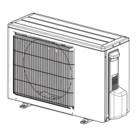
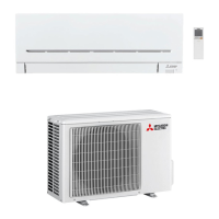
Do you have a question about the Mitsubishi Electric MUZ-AY25VG-ER1 and is the answer not in the manual?

Mitsubishi Electric MUZ-AY25VG-ER1 Specifications

General IconGeneral
CategoryAir Conditioner
ModelMUZ-AY25VG-ER1
TypeSplit System
Cooling Capacity2.5 kW
Heating Capacity3.2 kW
RefrigerantR32
Power Supply220-240 V, 50 Hz
Outdoor Unit Weight30 kg
Noise Level (Indoor Unit)19 dB

Summary

Servicing Precautions for Units Using Refrigerant R32

Information on Servicing

General safety checks and procedures for working with flammable refrigerants.

Leak Detection Methods

Details methods for detecting refrigerant leaks using electronic detectors and fluids.

Removal and Evacuation

Procedures for removing and evacuating refrigerant, including flushing with inert gas.

Specification

Wiring Diagram

Refrigerant System Diagram

Performance Curves

Actuator Control

Service Functions

Troubleshooting

12-1. Cautions on Troubleshooting

Essential safety precautions and checks before commencing troubleshooting.

12-2. Failure Mode Recall Function

Procedures for recalling and interpreting stored failure information.

12-3. Troubleshooting Check Table

A table correlating LED indications to abnormal points, conditions, and remedies.

12-4. Troubleshooting Criterion of Main Parts

Criteria and methods for checking the resistance/characteristics of key components.

12-5. Troubleshooting Flow

Step-by-step diagnostic flowcharts for checking various components and systems.

12-6. Test Point Diagram and Voltage

Diagrams showing test points on the inverter P.C. board and resistance charts.

Disassembly Instructions

Related product manuals