Do you have a question about the Mitsubishi Electric MUZ-FS15NAH and is the answer not in the manual?
| Category | Air Conditioner |
|---|---|
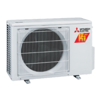
| Brand | Mitsubishi Electric |
| Model | MUZ-FS15NAH |
| Cooling Capacity | 15, 000 BTU/h |
| Refrigerant | R410A |
| Voltage | 208/230V |
| Hertz | 60 Hz |
| Phase | 1 |
| Indoor Unit Type | Wall-Mounted |
Presents cooling capacity data for various indoor/outdoor conditions.
Presents heating capacity data for various indoor/outdoor conditions.
Provides essential safety precautions before starting troubleshooting.
Lists symptoms, LED indications, conditions, and remedies for failures.
Specifies resistance and voltage criteria for testing key components.
Provides step-by-step diagnostic procedures for common issues.
Diagrams and voltage values for testing components on the inverter P.C. board.