Do you have a question about the Mitsubishi Electric MUZ-FH12NA and is the answer not in the manual?
| Brand | Mitsubishi Electric |
|---|---|
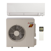
| Model | MUZ-FH12NA |
| Category | Air Conditioner |
| Language | English |
Outlines the specific indoor and outdoor air conditions used for performance testing.
Provides calculations for adjusting refrigerant charge based on piping length.
Tables listing cooling capacities under various operating conditions.
Tables listing heating capacities under various operating conditions.
Graphical representation of cooling performance vs. operating parameters.
Visual data on condensing pressure variations with temperature.
Graphical data for heating performance and pressure characteristics.
Summary of key electrical and operational data for all models.
Charts showing how compressor frequency affects capacity and input power.
Procedure for a special test run mode with fixed compressor frequency.
Details the timing and conditions for outdoor fan motor operation.
Describes the operation of the 4-way reversing valve in different modes.
Maps sensors to actuators, indicating their interaction for system functions.
Instructions for modifying the defrost finish temperature.
Guidance on enabling pre-heat control to protect the compressor.
Essential safety warnings and preliminary checks before troubleshooting.
Method to retrieve and interpret stored fault codes from the unit's memory.
A table detailing LED blinking patterns for outdoor unit faults and their remedies.
Cross-reference of symptoms, LED indications, abnormal points, and corrective actions.
Resistance and voltage specifications for testing critical components.
Visual guides for diagnosing specific problems step-by-step.
Diagrams showing test points and voltage readings on the inverter P.C. board.
Instructions for removing the outer panels and covers of the unit.
Procedures for accessing and removing the inverter components and circuit board.
Steps for detaching the Reversing Valve (R.V.) coil.
Guidance on removing temperature sensors from their mounting points.
Procedure for safely removing the outdoor fan motor assembly.
Instructions for safely removing the compressor and the 4-way valve.