EasyManua.ls Logo

Mitsubishi Electric MUZ-FH12NAH User Manual

Mitsubishi Electric MUZ-FH12NAH
58 pages
To Next Page IconTo Next Page
Page #1 background imageLoading...
Page #1 background image
SERVICE MANUAL
Models
OUTDOOR UNIT
Indoor unit service manual
MSZ-FH•NA Series (OBH683)
NOTE:
RoHS compliant products have <G> mark on the spec name plate.
HFC
utilized
R410A
No. OBH684
REVISED EDITION-C
PARTS CATALOG (OBB684)
MUZ-FH06NA
MUZ-FH09NA
MUZ-FH12NA
MUZ-FH06NAH
MUZ-FH09NAH
MUZ-FH12NAH
Please void OBH684 REVISED EDITION-B.
Revision C:
• MUZ-FH06NA, MUZ-FH09/12NA-
1
, MUZ-
FH18NA2, MUZ-FH06NAH, MUZ-
FH09/12NAH-
1
and MUZ-FH18NAH2
have been added.
MUZ-FH06NA
MUZ-FH09NA
MUZ-FH09NA
-
1
MUZ-FH12NA
MUZ-FH12NA
-
1
MUZ-FH15NA
MUZ-FH18NA
MUZ-FH18NA2
MUZ-FH06NAH
MUZ-FH09NAH
MUZ-FH09NAH
-
1
MUZ-FH12NAH
MUZ-FH12NAH
-
1
MUZ-FH15NAH
MUZ-FH18NAH
MUZ-FH18NAH2
CONTENTS
1. TECHNICAL CHANGES ······························2
2. PART NAMES AND FUNCTIONS ··················3
3. SPECIFICATION ········································4
4. OUTLINES AND DIMENSIONS ·····················6
5. WIRING DIAGRAM ·····································8
6. REFRIGERANT SYSTEM DIAGRAM ··········· 14
7. DATA······················································ 16
8. ACTUATOR CONTROL ····························· 27
9. SERVICE FUNCTIONS ······························ 28
10. TROUBLESHOOTING ······························· 29
11. DISASSEMBLY INSTRUCTIONS ················· 51

Other manuals for Mitsubishi Electric MUZ-FH12NAH

Question and Answer IconNeed help?

Do you have a question about the Mitsubishi Electric MUZ-FH12NAH and is the answer not in the manual?
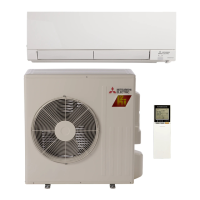
Mitsubishi Electric MUZ-FH12NAH Specifications

General IconGeneral
BrandMitsubishi Electric
ModelMUZ-FH12NAH
CategoryAir Conditioner
LanguageEnglish

Summary

TECHNICAL CHANGES

PART NAMES AND FUNCTIONS

SPECIFICATION

OUTLINES AND DIMENSIONS

WIRING DIAGRAM

REFRIGERANT SYSTEM DIAGRAM

DATA

7-1. PERFORMANCE DATA

Presents cooling capacity data at various indoor/outdoor conditions and corrections for piping length.

7-2. PERFORMANCE CURVE Cooling

Graphical representation of cooling capacity and power consumption versus outdoor conditions.

7-3. CONDENSING PRESSURE

Charts showing condensing and suction pressure based on indoor and outdoor temperatures.

7-4. STANDARD OPERATION DATA

Provides standard operating data for electrical circuits, refrigerant, and airflow across models.

7-5. CAPACITY AND INPUT CORRECTION BY INVERTER OUTPUT FREQUENCY

Illustrates how inverter frequency affects cooling and heating capacity and input power.

7-6. HOW TO OPERATE FIXED-FREQUENCY OPERATION (Test run operation)

Instructions for performing a test run operation using fixed-frequency settings.

ACTUATOR CONTROL

8-1. OUTDOOR FAN MOTOR CONTROL

Details the fan motor's ON/OFF operation interlocking with the compressor.

8-2. R.V. COIL CONTROL

Explains the 4-way valve operation for heating, cooling, and dry modes.

8-3. RELATION BETWEEN MAIN SENSOR AND ACTUATOR

Table showing sensor purpose and its relation to compressor, LEV, fan motor, and valve.

SERVICE FUNCTIONS

9-1. CHANGE IN DEFROST SETTING

Procedure to adjust the defrost finish temperature by modifying a jumper wire.

9-2. PRE-HEAT CONTROL SETTING

Instructions on how to activate pre-heat control to prevent compressor issues in low temperatures.

TROUBLESHOOTING

10-1. CAUTIONS ON TROUBLESHOOTING

Important safety and procedural checks before starting troubleshooting.

10-2. FAILURE MODE RECALL FUNCTION

Guide on how to recall and interpret stored failure codes from the unit's memory.

3. Outdoor unit failure mode table

Table listing outdoor unit failure modes, LED indications, conditions, and remedies.

10-3. TROUBLESHOOTING CHECK TABLE

A comprehensive table correlating symptoms, LED indications, and troubleshooting steps.

10-4. TROUBLE CRITERION OF MAIN PARTS

Provides resistance and voltage criteria for checking major components like thermistors and motors.

10-5. TROUBLESHOOTING FLOW

Step-by-step diagnostic flows for checking specific components like the inverter and compressor.

P Electromagnetic noise enters into TV sets or radios

Guidance on diagnosing and resolving electromagnetic noise interference affecting nearby electronic devices.

10-6. TEST POINT DIAGRAM AND VOLTAGE

Diagrams and voltage/resistance values for testing key points on the inverter P.C. board.

Related product manuals