Do you have a question about the Mitsubishi Electric MUZ-FH18NA2 and is the answer not in the manual?
| Brand | Mitsubishi Electric |
|---|---|
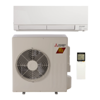
| Model | MUZ-FH18NA2 |
| Category | Air Conditioner |
| Language | English |
Table listing outdoor unit failure modes, symptoms, and remedies.
A table cross-referencing symptoms with LED indications and actions.
Criteria for checking the resistance and condition of main components.
Detailed step-by-step troubleshooting procedures for various issues.
Procedure to check the inverter and compressor.
Steps to diagnose an open phase condition in the inverter.
Guidance on checking the compressor's basic functionality.
Procedure to measure compressor winding resistance.
Method to measure compressor operation time until stop.
Steps to diagnose and resolve compressor start failures.
Procedure for checking the resistance of outdoor thermistors.
Diagnostic steps for the Reversing Valve (R.V.) coil.
Procedure to check the outdoor fan motor's resistance and voltage.