Do you have a question about the Mitsubishi Electric MUZ-FH35VE and is the answer not in the manual?
| Cooling Capacity | 3.5 kW |
|---|---|
| Heating Capacity | 4.0 kW |
| Energy Efficiency Rating (Cooling) | A+++ |
| SEER | 8.5 |
| Power Supply | 220-240 V, 50 Hz |
| Coefficient of Performance (Heating) | 4.0 |
| Refrigerant | R32 |
| Dimensions (Outdoor Unit) | 780×285×540 mm |
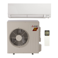
| Type | Split System Air Conditioner |
| Indoor Noise Level | 19 dB(A) |
Details the introduction of a new model version.
Presents curves for cooling capacity and input power.
Shows how compressor frequency affects capacity and input.
Guides on using test run and emergency operation modes.
Details unit current and low pressure under various conditions.
Explains fan motor operation linked to compressor status.
Describes reversing valve coil operation in cooling and heating.
Maps sensor inputs to actuator outputs for system control.
Instructions for adjusting the defrost finish temperature setting.
How to enable pre-heat control for low-temperature operation.
Essential safety and preparatory advice before troubleshooting.
Method for recalling and interpreting stored fault codes.
Table correlating symptoms, LED codes, conditions, and remedies.
Specifies resistance and voltage criteria for key components.
Step-by-step procedures for diagnosing specific component failures.
Diagrams showing test points and expected voltage/resistance values.
Procedure for removing the outer cabinet and service panel.
Steps to remove the inverter assembly and its main board.
Instructions for removing the reversing valve coil.
Procedures for removing various thermistors from the unit.
Steps to remove the outdoor fan motor and propeller.
Guide for removing the compressor and the 4-way valve.