Do you have a question about the Mitsubishi Electric MUZ-FH35VEHZ and is the answer not in the manual?
| Brand | Mitsubishi Electric |
|---|---|
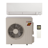
| Model | MUZ-FH35VEHZ |
| Category | Air Conditioner |
| Language | English |
Details on maximum refrigerant pipe length and height difference, and pipe sizes.
Guidelines for calculating additional refrigerant charge based on piping length.
Graphs showing how capacity and input vary with compressor frequency.
Instructions for performing test runs and operating the unit at fixed frequencies.
Charts illustrating outdoor low pressure and unit current under various conditions.
Tables detailing cooling performance data (capacity, input) at rated frequency under different conditions.
Tables detailing heating performance data (capacity, input) at rated frequency under different conditions.
Describes the fan motor's ON/OFF operation linked to the compressor.
Explains the control logic for the reversing valve coil during heating, cooling, and dry modes.
A table mapping sensors to actuators for various control purposes like protection and defrosting.
Instructions on how to adjust the defrost finish temperature by modifying the JS jumper wire.
Method to activate pre-heat control to prevent compressor issues at low temperatures.
Important safety precautions and preliminary checks before starting troubleshooting procedures.
Procedure to recall and display past error codes and abnormal conditions stored in the unit's memory.
A detailed table correlating LED indications and abnormal points with conditions, remedies, and recall functions.
Specifications and measurement criteria for key electrical components like thermistors, compressor, and motors.
Step-by-step diagnostic flowcharts for identifying and resolving specific faults in various components.
Diagnostic steps to check the inverter and compressor for proper operation and faults.
Procedures to test the resistance and function of various outdoor thermistors.
Steps to verify correct voltage supply to the unit and its electronic components.
Diagnostic process to identify and resolve issues related to wiring and communication errors.
Troubleshooting steps for the reversing valve coil and related components.
Procedures to diagnose and test the outdoor fan motor for proper functionality.
Steps to check the defrost heater and related circuit continuity and resistance.
Guidance on diagnosing issues related to refrigerant gas amount and circuit integrity.
Steps to identify and mitigate electromagnetic noise affecting external devices like TVs and radios.
Step-by-step guide for disassembling the outdoor unit cabinet and components for these models.
Step-by-step guide for disassembling the outdoor unit cabinet and components for this model.