EasyManua.ls Logo

Mitsubishi Electric MUZ-FH15NA User Manual

Mitsubishi Electric MUZ-FH15NA
58 pages
To Next Page IconTo Next Page
Page #1 background imageLoading...
Page #1 background image
SERVICE MANUAL
Models
OUTDOOR UNIT
Indoor unit service manual
MSZ-FH•NA Series (OBH683)
NOTE:
RoHS compliant products have <G> mark on the spec name plate.
HFC
utilized
R410A
No. OBH684
REVISED EDITION-C
PARTS CATALOG (OBB684)
MUZ-FH06NA
MUZ-FH09NA
MUZ-FH12NA
MUZ-FH06NAH
MUZ-FH09NAH
MUZ-FH12NAH
Please void OBH684 REVISED EDITION-B.
Revision C:
• MUZ-FH06NA, MUZ-FH09/12NA-
1
, MUZ-
FH18NA2, MUZ-FH06NAH, MUZ-
FH09/12NAH-
1
and MUZ-FH18NAH2
have been added.
MUZ-FH06NA
MUZ-FH09NA
MUZ-FH09NA
-
1
MUZ-FH12NA
MUZ-FH12NA
-
1
MUZ-FH15NA
MUZ-FH18NA
MUZ-FH18NA2
MUZ-FH06NAH
MUZ-FH09NAH
MUZ-FH09NAH
-
1
MUZ-FH12NAH
MUZ-FH12NAH
-
1
MUZ-FH15NAH
MUZ-FH18NAH
MUZ-FH18NAH2
CONTENTS
1. TECHNICAL CHANGES ······························2
2. PART NAMES AND FUNCTIONS ··················3
3. SPECIFICATION ········································4
4. OUTLINES AND DIMENSIONS ·····················6
5. WIRING DIAGRAM ·····································8
6. REFRIGERANT SYSTEM DIAGRAM ··········· 14
7. DATA······················································ 16
8. ACTUATOR CONTROL ····························· 27
9. SERVICE FUNCTIONS ······························ 28
10. TROUBLESHOOTING ······························· 29
11. DISASSEMBLY INSTRUCTIONS ················· 51

Other manuals for Mitsubishi Electric MUZ-FH15NA

Question and Answer IconNeed help?

Do you have a question about the Mitsubishi Electric MUZ-FH15NA and is the answer not in the manual?

Mitsubishi Electric MUZ-FH15NA Specifications

General IconGeneral
BrandMitsubishi Electric
ModelMUZ-FH15NA
CategoryAir Conditioner
LanguageEnglish

Summary

Technical Changes

New Model Additions

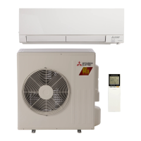
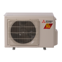
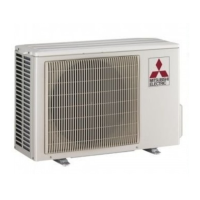
Details the addition of new outdoor unit models to the product line.

Service Part Number Updates

Information on changes and updates to service part numbers.

Specification

Data

Refrigerant Piping Specifications

Details maximum refrigerant piping length and height difference.

Cooling and Heating Performance Data

Presents cooling and heating capacity data and performance curves.

Pressure Charts and Operation Data

Condensing pressure charts (cooling/heating) and standard operation data.

Inverter and Test Operation Guidelines

Correction factors for inverter frequency and fixed-frequency operation guide.

Service Functions

Defrost Setting Adjustment

Instructions for changing the defrost finish temperature settings.

Pre-Heat Control Setting

Guide to activating or deactivating the pre-heat control function.

Troubleshooting

Troubleshooting Cautions and Procedures

Important safety precautions, failure mode recall, and basic checks.

Failure Mode Identification

Tables detailing failure modes, conditions, LED indications, and remedies.

Component Diagnosis and Troubleshooting Flow

Criteria for main parts, and flowcharts for diagnosing issues.

Specific Component Checks

Procedures for checking miswiring, signal errors, heaters, refrigerant circuits, and noise.

Test Point Diagrams and Voltage Checks

Diagrams and voltage check points for the inverter P.C. board components.

Disassembly Instructions

Terminal and Panel Removal

Instructions for detaching terminals and removing outer panels.

Inverter, Coil, and Thermistor Removal

Procedures for removing the inverter, R.V. coil, and various thermistors.

Fan Motor, Compressor, and Valve Removal

Steps for removing the outdoor fan motor, compressor, and 4-way valve.

Related product manuals