EasyManua.ls Logo

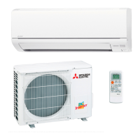
Mitsubishi Electric MUZ-HR VF Series User Manual

Mitsubishi Electric MUZ-HR VF Series
42 pages
To Next Page IconTo Next Page
Page #1 background imageLoading...
Page #1 background image
Models
MSZ-HR25VF
-
E1
,
ER1
,
ET1
MSZ-HR35VF
-
E1
,
ER1
,
ET1
MSZ-HR42VF
-
E1
,
ER1
,
ET1
MSZ-HR50VF
-
E1
,
ER1
,
ET1
MSZ-HR60VF
-
E1
,
ER1
,
ET1
MSZ-HR71VF
-
E1
,
ER1
,
ET1
INDOOR UNIT
No. OBH822
REVISED EDITION-B
Outdoor unit service manual
MUZ-HR∙VF Series (OBH823)
MXZ-HA∙VF Series (OBH828)
PARTS CATALOG (OBB822)
CONTENTS
1. TECHNICAL CHANGES ······························2
2. PART NAMES AND FUNCTIONS ··················3
3. SPECIFICATION ········································4
4. NOISE CRITERIA CURVES ··························6
5. OUTLINES AND DIMENSIONS ·····················8
6. WIRING DIAGRAM ·····································9
7. REFRIGERANT SYSTEM DIAGRAM ··········· 10
8. SERVICE FUNCTIONS ······························ 11
9. MICROPROCESSOR CONTROL ················ 13
10. TROUBLESHOOTING ······························· 17
11. DISASSEMBLY INSTRUCTIONS ················· 34
SERVICE MANUAL
MSZ-HR25VF
Revision B:
• MSZ-HR60/71VF-
ER1
have been added.
OBH822 REVISED EDITION-A is void.
Question and Answer IconNeed help?

Do you have a question about the Mitsubishi Electric MUZ-HR VF Series and is the answer not in the manual?

Mitsubishi Electric MUZ-HR VF Series Specifications

General IconGeneral
RefrigerantR32
Cooling CapacityVaries by model (e.g., 2.5kW, 3.5kW, 5.0kW, etc.)
Heating CapacityVaries by model (e.g., 3.2kW, 4.0kW, 6.0kW, etc.)
Indoor Unit Noise LevelAs low as 19 dB(A)
Outdoor Unit Noise LevelVaries by model
Power Supply220-240V, 50Hz
Energy Efficiency Ratio (EER)Varies by model
Coefficient of Performance (COP)Varies by model
Indoor Unit Dimensions (HxWxD)Varies by model
Outdoor Unit Dimensions (HxWxD)Varies by model
Indoor Unit WeightVaries by model
Outdoor Unit WeightVaries by model

Summary

1 TECHNICAL CHANGES

2 PART NAMES AND FUNCTIONS

3 SPECIFICATION

4 NOISE CRITERIA CURVES

5 OUTLINES AND DIMENSIONS

6 WIRING DIAGRAM

7 REFRIGERANT SYSTEM DIAGRAM

8 SERVICE FUNCTIONS

8-1. TIMER SHORT MODE

Enables shortening of timer set times for service purposes.

8-2. P.C. BOARD MODIFICATION FOR INDIVIDUAL OPERATION

Modifies remote controller PC boards for multi-unit operation.

8-3. AUTO RESTART FUNCTION

Configures the unit to resume previous operation settings after power interruption.

9 MICROPROCESSOR CONTROL

Wireless Remote Controller Operation

Details functions and usage of the wireless remote controller for unit management.

Indoor Unit Display and Indicators

Explains the visual signals and indicators on the indoor unit.

Standard Operation Modes

Covers Cool, Dry, Fan, and Heat modes, including their specific functions.

Advanced Operation Features

Explains multi-system, auto vane, timer, emergency, and time delay operations.

10 TROUBLESHOOTING

10-1. CAUTIONS ON TROUBLESHOOTING

Important safety and procedural notes before starting troubleshooting.

10-2. FAILURE MODE RECALL FUNCTION

How to recall and interpret stored error codes for diagnosis.

Diagnostic Flowcharts and Tables

Step-by-step guides, flowcharts, and check tables for diagnosing unit issues.

10-7. TEST POINT DIAGRAM AND VOLTAGE

Diagrams and voltage specifications for testing electronic components.

Electromagnetic Noise Interference

11 DISASSEMBLY INSTRUCTIONS

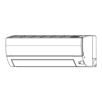
11-1. MSZ-HR25VF MSZ-HR35VF MSZ-HR42VF MSZ-HR50VF

Procedures for disassembling specific indoor unit models.
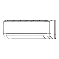
11-2. MSZ-HR60VF MSZ-HR71VF

Procedures for disassembling specific indoor unit models.
Related product manuals