129
Defrost thermistor (RT61)
Fin temperature thermistor (RT64)
Ambient temperature
thermistor (RT65)
Outdoor heat exchanger temperature
thermistor (RT68)
Gas pipe temperature thermistor
(RT6A~D)
MXZ-3A54VA-
E1
,
E2
,
E3
MXZ-4A71VA-
E1
,
E2
,
E3
MXZ-4A80VA-
E1
2A40VA-
E1
2A52VA
Discharge temperature
thermistor (RT62)
WHT - RED
RED - ORN
Measure the resistance using a tester. (Part temperature : -10°C ~ 40°C)
37.4
~ 53.9
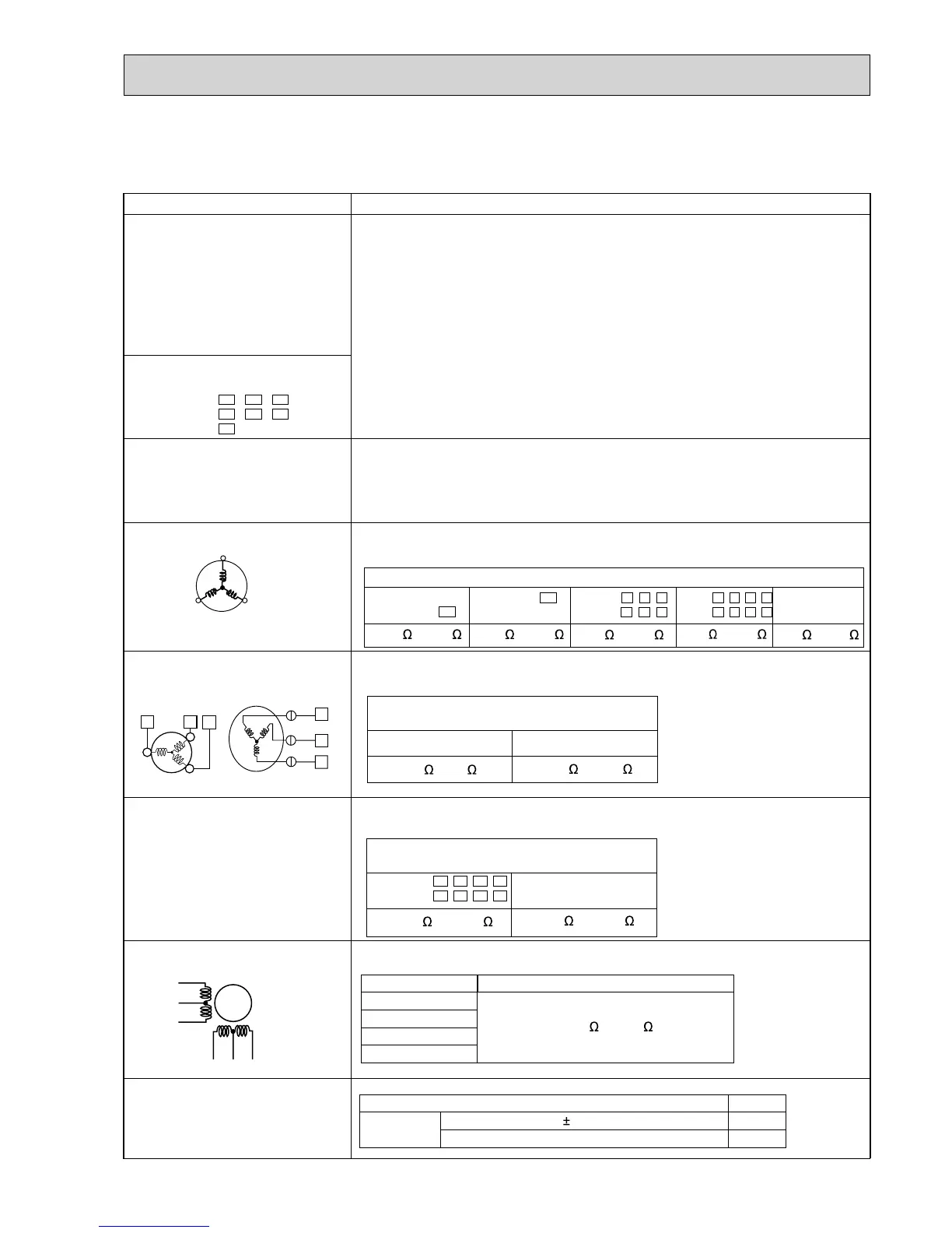
Part name
Check method and criterion
Measure the resistance between terminals using a tester.
(Winding temperature : -10°C ~ 40°C)
Compressor
W
U
V
WHT
RED
BLK
Measure the resistance between lead wires using a tester.
(Part temperature : -10°C ~ 40°C)
Outdoor fan motor
R.V. coil
Measure the resistance using a tester. (Part temperature : -10°C ~ 40°C)
Linear expansion valve
LEV
WHT
RED
YLW
BRN
ORN
BLU
Color of lead wire
Normal
YLW - BRN
BRN - BLU
U
RED
WHT
BLK
V
W
(W)
(V)
(U)
Normal (Each phase)
13.4 ~ 16.4
High pressure switch (HPS)
MXZ-4A80/5A100
Pressure Normal
HPS
3.7 0.15 MPa
4.8 MPa
Open
Close
+ 0.05
-
0.1
13-5. TROUBLE CRITERION OF MAIN PARTS
MXZ-2A30VA MXZ-2A40VA MXZ-2A52VA MXZ-3A54VA MXZ-4A71VA MXZ-4A80VA
MXZ-5A100VA
MXZ-3A/4A/5A
12 ~ 16
MXZ-2A
Measure the resistance with a tester.
Refer to 13-7. “Test point diagram and voltage”, 1. “Inverter P.C. board” , 2. “Outdoor
electronic control P.C. board” or 5. “Outdoor Power board”, for the chart of thermistor.
Measure the resistance with a tester.
Before measurement, hold the thermistor with your hands to warm it up.
Refer to 13-7. “Test point diagram and voltage”, 1. “Inverter P.C. board” or 2. “Outdoor
electronic control P.C. board”, for the chart of thermistor.
23
W
U
V
1
WHT
RED BL