Do you have a question about the Mitsubishi Electric MXZ-3A54VA and is the answer not in the manual?
| Series | MXZ |
|---|---|
| Cooling Capacity | 5.4 kW |
| Power Supply | 220-240 V, 50 Hz |
| Refrigerant | R410A |
| Number of Connectable Indoor Units | 3 |
| Cooling Capacity (BTU) | 18400 BTU |
| Noise Level (Outdoor) | 49 dB |
Lists and describes tools specifically required for R410A refrigerant systems.
Covers specifications for refrigerant piping, flaring, refrigeration oil, and air purging procedures.
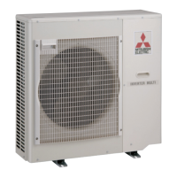
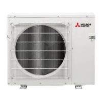
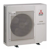
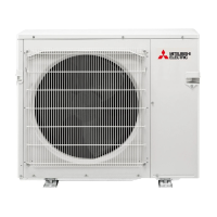
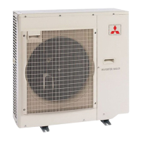
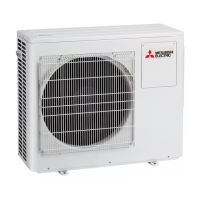
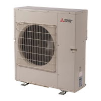
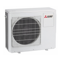
Provides visual diagrams labeling key components of different outdoor unit models.
Details combinations, capacities, and electrical data for various indoor unit configurations.
Lists key specifications like model, power supply, capacity, dimensions, weight, and refrigerant details.
Displays octave band sound pressure level curves for different outdoor unit models.
Provides diagrams and dimensions for installing outdoor units, including space requirements.
Provides wiring diagrams for various outdoor unit models, identifying components and connections.
Provides guidelines for refrigerant piping lengths, bending points, and additional charge calculations.
Details standard conditions for performance curves, including voltage, airflow, and main temperature readings.
Displays graphs illustrating capacity and input correction factors based on temperatures.
Shows how capacity and input change with inverter frequency for different unit classes.
Provides instructions for performing a test run operation to check system functionality.
Presents graphs showing outdoor low pressure and current based on ambient conditions.
Shows operating conditions and test run procedures specific to the HEAT mode.
A table mapping sensors to their corresponding actuators for various outdoor unit models.
Explains how to lock the outdoor unit's operation mode (COOL/DRY or HEAT) for consistent performance.
Details how to activate a function to reduce outdoor unit noise, potentially affecting capacity.
Describes the pre-heat function to prevent compressor issues in cold conditions and how to activate/deactivate it.
Explains the automatic detection and correction of improper wiring or piping for improved operation.
Describes how to increase maximum compressor frequency and fan speed to improve unit capacity.
Details how to adjust defrost parameters to optimize heating performance.
Explains how to adjust the outdoor unit's current limit, useful when current exceeds allowed values.
Outlines important safety precautions and checks to perform before starting troubleshooting.
Explains how to recall and interpret stored failure codes from the unit's memory for diagnosis.
Lists common outdoor unit failure modes, LED indications, conditions, and correspondence for troubleshooting.
Provides a step-by-step guide to diagnose and resolve common outdoor unit operational issues.
A comprehensive table listing symptoms, abnormal points, conditions, and troubleshooting steps.
Details the resistance and voltage criteria for testing key components like thermistors, compressor, and fan motor.
Offers diagnostic flowcharts for specific troubleshooting scenarios like outdoor unit non-operation.
Guides on how to check for miswiring and serial signal errors when the outdoor unit does not operate.
Provides a procedure to check the resistance and operation of the R.V. coil for troubleshooting heating/cooling issues.
Details the steps to check the LEV coil for proper operation, including sound and resistance tests.
Guides on checking compressor winding resistance and inverter board voltage for diagnosing compressor issues.
Provides a procedure to measure thermistor resistance and identify abnormal conditions.
Details troubleshooting steps for outdoor fan motor issues, including resistance and voltage checks.
Outlines how to check the high-pressure switch for proper operation and potential faults.
Guides on checking bus-bar voltage and confirming LED indications for troubleshooting.
Illustrates test points and voltage measurements on the inverter P.C. board for diagnostic purposes.
Shows the layout and test points for the outdoor electronic control P.C. board, including thermistor connections.
Illustrates the layout and test points for the P.C. boards of MXZ-4A80VA and MXZ-5A100VA units.
Details the layout and connections of the noise filter P.C. board for different outdoor unit models.
Shows the layout and test points for the power P.C. board of MXZ-2A and MXZ-4A/5A series units.
Illustrates the layout and connection points for the outdoor power board, including compressor and controller connections.
Shows the layout and connections for the display P.C. board.
Details the layout and connections for the interface P.C. board.
Outlines the procedure for removing the cabinet, top panel, and other parts from MXZ-2A series outdoor units.
Details the steps for removing the inverter assembly, inverter P.C. board, and power P.C. board.
Details the procedure for removing the compressor and the 4-way valve.
Outlines compressor removal steps for MXZ-3A54VA and MXZ-4A71VA models.
Details the procedure for removing the outdoor fan motor.
Details the procedure for removing the reactor.
Outlines compressor removal steps for MXZ-4A80VA and MXZ-5A100VA models.
Lists structural and functional components for MXZ-2A series outdoor units with diagrams.
Lists electrical components and part numbers for MXZ-2A series outdoor units.
Identifies the drain socket part number for MXZ-2A series outdoor units.
Lists structural and functional parts for MXZ-3A54VA and MXZ-4A71VA outdoor units.
Lists functional and electrical parts for MXZ-3A54VA and MXZ-4A71VA outdoor units.
Lists accessory parts for MXZ-3A54VA and MXZ-4A71VA outdoor units.
Lists structural and functional parts for the MXZ-4A80VA outdoor unit with a diagram.
Lists functional and electrical parts for the MXZ-4A80VA outdoor unit.
Lists accessory parts for the MXZ-4A80VA outdoor unit.
Details specifications for different-diameter pipes, including lengths and connected pipe diameters.
Describes the purpose of the outlet guide and provides dimensional information for specific models.