Do you have a question about the Mitsubishi Electric NTXMSM36A142BA and is the answer not in the manual?
General safety rules to observe before performing maintenance or accessing electrical components.
Specific safety precautions for handling R410A refrigerant and associated equipment.
Instructions for configuring the auxiliary heating function and related settings.
Flowchart to determine and select appropriate unit capacities for cooling and heating.
Guidance on setting model selection switches on the unit.
Guidelines and diagrams for setting up the transmission system wiring.
Essential checks and procedures to perform before conducting a system test run.
Explanations of error codes and corresponding corrective actions.
Step-by-step flowcharts for diagnosing system faults.
General principles and considerations for power wiring.
Details concerning wiring for main power supply and equipment capacity.
Information on the types and specifications of transmission cables.
Procedures and guidelines for setting system switches.
Overview of the refrigerant piping system configuration.
Guidance on selecting the appropriate refrigerant branch kits.
Instructions for selecting refrigerant piping for different system sections.
Calculation methods and procedures for adding refrigerant.
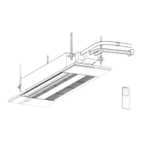
Steps to remove outer panels for accessing internal components.
Procedure for safely removing the fan motor assembly.
Steps to remove the housing for electrical components.
Detailed steps for safely removing the compressor.
Procedure for removing the accumulator component.
Instructions and precautions for replacing the fusible plug.
Explanation of remote controller features, buttons, and interface.
Guide to understanding the remote controller's display icons and modes.
Navigation paths and structure of the remote controller menus.
Instructions on how to view and interpret system error codes.
Steps to access and utilize the service menu functions.
Procedures for performing system test runs for diagnosis.
How to configure various unit functions via the remote controller.
Methods for viewing and clearing system error logs.
Procedures for performing system self-diagnosis and interpreting results.
Procedure for diagnosing the remote controller's functionality.
Accessing and utilizing smooth maintenance data and features.
Method for requesting and viewing specific operational data.
| Category | Air Conditioner |
|---|---|
| Cooling Capacity | 3.6 kW |
| Heating Capacity | 4.2 kW |
| Power Supply | 220-240V, 50Hz |
| Energy Efficiency Ratio (Cooling) | 3.21 |
| Refrigerant | R32 |
| Indoor Unit Dimensions (HxWxD) | 290x799x232 mm |
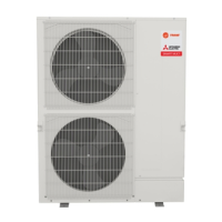
| Outdoor Unit Dimensions (HxWxD) | 550 x 800 x 285 mm |
| Indoor Unit Weight | 9 kg |
| Noise Level (Outdoor Unit) | 49 dB(A) |