EasyManua.ls Logo

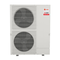
Mitsubishi Electric NTXMSH36A142BA User Manual

Mitsubishi Electric NTXMSH36A142BA
190 pages
To Next Page IconTo Next Page
Page #1 background imageLoading...
Page #1 background image
TECHNICAL & SERVICE MANUAL
OUTDOOR UNIT
No. OCHT810
REVISED EDITION-A
HFC
utilized
R410A
September 2023
Note:
Specifications have been
changed in REVISED
EDITION-A.
Model name
indication
PARTS CATALOG (OCBT810)
CONTENTS
1. SAFETY PRECAUTION ·······················2
2. OVERVIEW OF UNITS ························5
3. SPECIFICATIONS ···························· 11
4. DATA ·············································· 14
5. OUTLINES AND DIMENSIONS ··········· 36
6. WIRING DIAGRAM ··························· 37
7. NECESSARY CONDITIONS
FOR SYSTEM CONSTRUCTION ········· 40
8. TROUBLESHOOTING ······················· 55
9. ELECTRICAL WIRING ·····················133
10. REFRIGERANT PIPING TASKS ·········139
11. DISASSEMBLY PROCEDURE ···········147
12. REMOTE CONTROLLER ··················168
<Outdoor unit>
[Model Name]
NTXMSM36A142BA
NTXMSM48A182BA
NTXMSM60A182BA
NTXMSH36A142BA
NTXMSH42A152BA
NTXMSH48A182BA
OCHT810 is void.
Question and Answer IconNeed help?

Do you have a question about the Mitsubishi Electric NTXMSH36A142BA and is the answer not in the manual?

Mitsubishi Electric NTXMSH36A142BA Specifications

General IconGeneral
CategoryAir Conditioner
Cooling Capacity3.6 kW
Heating Capacity4.2 kW
Power Supply220-240 V, 50 Hz
RefrigerantR32

Summary

TECHNICAL & SERVICE MANUAL

1 SAFETY PRECAUTION

1-1. ALWAYS OBSERVE FOR SAFETY

General safety guidelines to follow before accessing the unit for maintenance or repair.

1-2. CAUTIONS RELATED TO NEW REFRIGERANT

Specific precautions when working with refrigerant R410A, including tool usage and pipe handling.

Cautions for refrigerant piping work

2-2. SYSTEM CONSTRUCTION

2-3 SYSTEM CONSTRUCTION( BRANCH BOX SYSTEM)

2-4. SYSTEM SPECIFICATIONS

(1) Outdoor Unit

Provides cooling and heating capacities for various outdoor unit models under specified conditions.

3 SPECIFICATIONS

Service Ref. NTXMSM36A142BA NTXMSM48A182BA

Detailed specifications for NTXMSM36A142BA and NTXMSM48A182BA outdoor units, including electrical and mechanical data.

3 SPECIFICATIONS (continuation)

Service Ref. NTXMSH36A142BA NTXMSH42A152BA NTXMSH48A182BA

Detailed specifications for NTXMSH36A142BA, NTXMSH42A152BA, and NTXMSH48A182BA outdoor units.

Service Ref. NTXMSM60A182BA

Detailed specifications for the NTXMSM60A182BA outdoor unit, covering electrical, mechanical, and operational data.

4 DATA

4-1. SELECTION OF COOLING/HEATING UNITS

Flowchart and guidelines for selecting indoor and outdoor units based on total capacity and room loads.

4-1. SELECTION OF COOLING/HEATING UNITS (continuation)

How to determine the capacity when greater than 100% indoor model size units are connected in total:

Flowchart for determining system capacity when indoor units exceed outdoor unit capacity by more than 100%.

2. Heating Calculation

(6) Determination of Maximum System Capacity

Compares total indoor unit capacity with total outdoor unit capacity to determine the maximum system capacity.

4-2. CORRECTION BY TEMPERATURE

4-3. STANDARD OPERATION DATA (REFERENCE DATA)

4-4. STANDARD CAPACITY DIAGRAM

4-5. CORRECTING CAPACITY FOR CHANGES IN THE LENGTH OF REFRIGERANT PIPING

5 OUTLINES AND DIMENSIONS

6 WIRING DIAGRAM

6 WIRING DIAGRAM (continuation)

7 NECESSARY CONDITIONS FOR SYSTEM CONSTRUCTION

7-1. TRANSMISSION SYSTEM SETUP

Guidelines for setting up the transmission system, including M-NET cable connections, address settings, and wiring.

7-3. REFRIGERANT SYSTEM DIAGRAM

NTXMSM36A142BA NTXMSH42A152BA NTXMSH48A182BA

NTXMSM60A182BA

7-4. SYSTEM CONTROL

7-4-1. Example for the System

Examples of M-NET remote controller system wiring, methods, and address settings.

D. Example of a group operation with 2 or more outdoor units and an MA remote controller.

C. Example of an MA remote controller system (address setting is not necessary.)

Wiring Method and Address Setting

Wiring methods and address settings for MA remote controller systems, including standard, multiple controller, and group operations.

E. Example of a system using Branch Box and A-Control indoor unit

Wiring Method Address Settings

Details wiring methods and address settings for systems using Branch Boxes and A-Control indoor units.

8 TROUBLESHOOTING

8-1. CHECKPOINTS FOR TEST RUN

Procedures and safety checks to perform before initiating a test run of the air conditioning system.

8-1-2. Countermeasures For Error During Test Run

8-1-3. SELF-DIAGNOSIS ACTION BY FLOWCHART

Check code 0403 (Ed) Serial communication error or Model selection SW error

Troubleshooting flowchart for serial communication errors or model selection switch errors, detailing diagnosis and remedy steps.

Check code 1102 (U2) Compressor temperature trouble

Check code 1102 (U2) Compressor temperature trouble (Chart 2 of 2)

Check code 1302 (UE) High pressure trouble or thermal protector trouble

Check code 1302 (UE) High pressure trouble or thermal protector trouble (Chart 2 of 4)

Check code 1302 (UE) High pressure trouble or thermal protector trouble (Chart 3 of 4)

Check code 1302 (UE) High pressure trouble or thermal protector trouble (Chart 4 of 4)

Check code 1500 (U7) Superheat due to low discharge temperature trouble

Check code 1500 (U7) Superheat due to low discharge temperature trouble (Chart 2 of 2)

Check code 1501 (U2) Refrigerant shortage trouble

Check code 1501 (U2) Refrigerant shortage trouble (Chart 2 of 2)

Check code 1501 (U2) Closed valve in cooling mode

Check code 1503 (P6) Freeze protection of Branch box or Indoor unit

Check code 1508 (EF) 4-way valve trouble in heating mode

Check code 3121 Out-of-range outside air temperature

Check code 4100 (UF) Compressor current interruption (Locked compressor)

Check code 4100 (UF) Compressor current interruption (Locked compressor) (Chart 2 of 2)

Check code 4210 (UP) Compressor overcurrent interruption/failure in 12 VDC power supply circuit on power circuit board

Check code 4210 (UP) Compressor overcurrent interruption/failure in 12 VDC power supply circuit on power circuit board (Chart 2 of 2)

Check code 4220 (U9) Voltage shortage /Overvoltage/PAM error/L1 open phase/primary current sensor error/Power synchronization signal error

Check code 4220 (U9) Voltage shortage/overvoltage/PAM error/L1 open phase/primary current sensor error/Power synchronization signal error (Chart 2 of 2)

Check code 4230 (U5) Heat sink temperature trouble

Check code 4250 (U6) Power module trouble or overcurrent trouble

Check code 4400 (U8) Fan trouble

Check code 5101 (U3) Compressor temperature thermistor (TH4) open/short

Check code 5102 (U4) Suction pipe temperature thermistor (TH6) open/short

Check code 5105 (U4) Outdoor liquid pipe temperature thermistor (TH3) open/short

Check code 5106 (U4) Ambient temperature thermistor (TH7) open/short

Check code 5109 (U4) HIC pipe temperature thermistor (TH2) open/short

Check code 5110 (U4) Heat sink temperature thermistor(TH8) open/short

Check code 5201 (F5) High pressure sensor (63HS) trouble

Check code 5202 (F3) Low pressure sensor (63LS) trouble

Check code 5300 (UH) Primary current error

Check code 6600 (A0) Duplex address error

Check code 6602 (A2) Transmission processor hardware error

Check code 6603 (A3) Transmission bus BUSY error

Check code 6606 (A6) Signal communication error with transmission processor

Check code 6607 (A7) No ACK error

Check code 6607 (A7) No ACK error (Chart 2 of 4)

Check code 6607 (A7) No ACK error (Chart 3 of 4)

Check code 6607 (A7) No ACK error (Chart 4 of 4)

Check code 6608 (A8) No response frame error

Check code 6831, 6834 (E0/E4) MA communication receive error

Check code 6831, 6834 (E0/E4) MA communication receive error (Chart 2 of 2)

Check code 6832, 6833 (E3/E5) MA communication send error

Check code 6832, 6833 (E3/E5) MA communication send error (Chart 2 of 2)

Check code 7100 (EF) Total capacity error

Check code 7101 (EF) Capacity code error

Check code 7102 (EF) Connecting excessive number of units and branch boxes

Causes and checkpoints

Causes and checks for errors related to exceeding the number of connected indoor units or branch boxes, and M-NET line connection.

Check code 7105 (EF) Address setting error

Check code 7130 (EF) Incompatible unit combination error

●Diagnosis of defects

Troubleshooting for incompatible unit combinations, checking authorization and model selection switch settings.

8-5. INTERNAL SWITCH FUNCTION TABLE

8-6. OUTDOOR UNIT INPUT/OUTPUT CONNECTOR

8-7. HOW TO CHECK PARTS

Check method of DC fan motor (fan motor/outdoor multi controller circuit board)

Check method of multi controller circuit board

Check method of power circuit board

Check method of M-NET power circuit board

8-8. HOW TO CHECK COMPONENTS

<LOW PRESSURE SENSOR>

• Comparing the Low Pressure Sensor Measurement and Gauge Pressure

Explains how to compare low pressure sensor readings with gauge pressure and troubleshoot sensor or connector issues.

<HIGH PRESSURE SENSOR>

• Comparing the High Pressure Sensor Measurement and Gauge Pressure

Details how to compare high pressure sensor readings with gauge pressure and troubleshoot sensor or controller board issues.

8-9. TEST POINT DIAGRAM

Outdoor power circuit board

Brief Check of POWER MODULE

Details checks for the power module, including diode, IGBT, and inverter circuits, and resistance measurements of various points.

Outdoor noise filter circuit board

M-NET power circuit board

9 ELECTRICAL WIRING

9-2-2. Cross section area of Wire for Main Power and ON/OFF capacities

9-3. DESIGN FOR CONTROL WIRING

9-4. WIRING TRANSMISSION CABLES

9-5. SYSTEM SWITCH SETTING

9-6. EXAMPLE EXTERNAL WIRING DIAGRAM FOR A BASIC SYSTEM

Provides example external wiring diagrams for basic systems using M-NET controllers or Branch Boxes with A-Control indoor units.

10 REFRIGERANT PIPING TASKS

10-1-2. NTXMSM60A182BA

10-2. PRECAUTIONS AGAINST REFRIGERANT LEAKAGE

11 DISASSEMBLY PROCEDURE

OPERATING PROCEDURE PHOTOS/FIGURES

4. Removing the thermistor <Suction pipe> (TH6)

Procedure for removing the suction pipe thermistor (TH6), including connector disconnection and sensor holder removal.

6. Removing the thermistor <Outdoor liquid pipe> (TH3) and thermistor <Compressor> (TH4), thermistor <HIC pipe> (TH2)

Steps for removing outdoor liquid pipe, compressor, and HIC pipe thermistors, including connector disconnections and sensor holder removal.

9. Removing bypass valve coil (SV1) and bypass valve

Step-by-step instructions for removing the bypass valve coil (SV1) and the bypass valve, including connector disconnection and refrigerant recovery.

13. Removing the compressor (MC)

Procedure for removing the compressor, including removing felt, thermistor, thermal protector, lead wires, and welded pipes.

16. Changing the fusible plug

Instructions for changing the fusible plug, emphasizing safety precautions regarding heat exposure and tightening torque.

17. Removing the thermal protector (TRS)

Steps for removing the thermal protector (TRS), including disconnecting connectors and pulling it from the holder.

9. Removing bypass valve coil (SV1, SV2) and bypass valve

Instructions for removing bypass valve coils and the bypass valve, including connector disconnection and refrigerant recovery.

14. Removing the accumulator

Steps for removing the accumulator, including disconnecting electrical parts box, valve bed, and welded pipes.

16. Removing the base heater

Steps for removing the base heater, including fan motor, motor support, and base heater cover removal.

17. Changing the fusible plug

Instructions for changing the fusible plug, emphasizing safety precautions regarding heat exposure and tightening torque.

12 REMOTE CONTROLLER

12-1. REMOTE CONTROLLER FUNCTIONS

Describes the controller interface, function buttons, display modes, and various icons for the TAR-40MAA remote controller.

12-2. ERROR INFORMATION

· Checking the error information

12-3. SERVICE MENU

12-4. TEST RUN

12-4-2. PAR-FL32MA

12-5. FUNCTION SETTING

12-5-1. TAR-40MAA

Explains how to set functions for the TAR-40MAA remote controller, including refrigerant addresses, unit numbers, and mode settings.

12-5-2. PAR-FL32MA

12-5-3. PAR-SL101A-E

12-6. ERROR HISTORY

12-7. SELF-DIAGNOSIS

<Malfunction-diagnosis method at maintenance service>

12-7-2. PAR-FL32MA

Details malfunction diagnosis procedures for the PAR-FL32MA remote controller, including checking refrigerant address and operation.

12-8. REMOTE CONTROLLER CHECK

12-9. SMOOTH MAINTENANCE

12-10. REQUEST CODE

2. Set the Refrigerant address and Request code.

Guides on setting refrigerant addresses and requesting codes to view operation data and error history via the remote controller.

Related product manuals