Do you have a question about the Mitsubishi Electric NTXMSM60A182BA and is the answer not in the manual?
| Phase | 1 |
|---|---|
| Refrigerant | R410A |
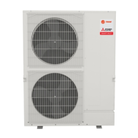
| Type | Split System |
| Cooling Capacity (BTU) | 18000 |
| Heating Capacity (BTU) | 20000 |
| Voltage (V) | 208-230V |
Safety precautions specific to R410A refrigerant and related procedures.
Lists error codes and their corresponding troubleshooting steps and countermeasures.
Flowcharts to diagnose and resolve specific self-diagnosis errors like serial communication issues.
Calculation and procedure for adding refrigerant charge based on pipe length and indoor unit capacity.
Guide to viewing and resetting error codes displayed on the remote controller.
Guide to accessing and navigating the service menu, including password entry.
Procedures for performing test runs in cool, heat, and auto vane modes.
How to view and delete error history records from the remote controller.
Procedures for performing self-diagnosis on the air conditioner system.