1 2
3 4
5 6
7 8
CITY MULTI Control System
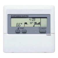
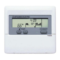
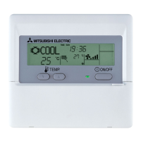
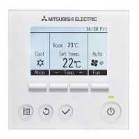
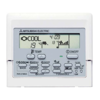
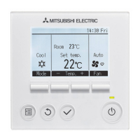
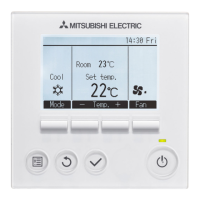
ME Remote Controller PAR-F27MEA
Installation Manual
This manual describes installation of the ME remote controller that connects to CITY MULTI air conditioner indoor unit. Please read this manual
thoroughly and install the remote controller accordingly. For information on how to wire and install the air conditioning units, refer to the installation
manual for them.
1 Safety Precautions
● Read these Safety Precautions and perform installation work accordingly.
● The following two symbols are used to dangers that may be caused by incorrect use and their degree:
WARNING
This symbol denotes what could lead to serious injury or death if you misuse the PAR-F27MEA.
CAUTION
This symbol denotes what could lead to a personal injury or damage to your property if you misuse the PAR-F27MEA.
● After reading this installation manual, give it and the indoor unit installation manual to the end user.
● The end user should keep this manual and the indoor unit installation manual in a place where he or she can see it at anytime. When someone moves
or repairs the PAR-F27MEA, make sure that this manual is forwarded to the end user.
(B) Interlocked registration information confirmation
After performing step 6, proceed as follows:
BB
BB
B Display the indoor unit address No. you want to confirm.
- Press the H [Time selection (
) and ( )] buttons. The inter-
locked unit address decreases and increases. Set it to the in-
door unit address No. you want to confirm.
CC
CC
C Displaying the LOSSNAY address No. interlocked at step
BB
BB
B.
- Press the E [Timer selection ( )] button. The interlocked
LOSSNAY address No. and indoor unit address No. are alter-
nately displayed.
DD
DD
D Displaying another registered unit address No.
- After step C, press the E [Timer selection ( )] button again.
Another registered unit address No. is displayed.
(The display method is the same as step C.)
NOTE: Acquire the cable for ME remote controller at the site.
Only use cables that meet the following specifications:
Specifications (CVV, shielded wire CVVS, CPEVS)
1.25mm
2
may only be used as an extension for the section beyond 10 m.
• Under 10 m --- 0.3 ~ 0.75 mm
2
2-core cable (CVV)
• Beyond 10 m --- 1.25 mm
2
2-core cable (CVVS, CPEVS)
Cables with a diameter of up to 1.25 mm
2
may be used for remote control wiring, although 0.75 mm
2
or less is recommended for easier
handling.
* CVV is a control cable which is sheathed in polyvinyl chloride with polyvinyl insulated wires inside.
4 How To Install
1. Chose a place in which to install the remote controller (switch box).
Be sure to observe the following steps:
(1) Temperature sensors are provided with both the remote controller and the indoor units. When using the
remote controller temperature sensor, the master remote controller detects the room temperature.
Install the master remote controller in a place where the average room temperature can be detected
and which is not affected by any heat source from direct sunlight or air blown from air conditioning units.
(For how to set the master and subordinate remote controller, see step 6 in section 4 How To Install .
For how to set the temperature sensor, refer to the CITY MULTI indoor unit installation manual.)
(2) When installing on either the switch box or the wall, allow extra space around the remote controller as
shown in the figure at the right.
(When using the remote controller in combination with a Program timer, refer to the Program timer
installation manual.)
NOTE: Make sure that there is no wiring or wire near the remote controller sensor. If there is, the remote controller cannot detect the exact room
temperature.
(3) Parts which must be supplied on site.
• Switch box for two units
• Thin-copper wir ing pipe
• Lock nut and bushing
2 Confirming the Supplied Parts
Confirm that the box includes the following parts, in addition to this installation manual:
1. Remote controller (cover, body) ..................................................................................... 1
2. Cross recessed pan head screw (M4 × 30) .................................................................... 2
3. Wood screw (4.1 × 16, used for directly hooking to the wall) ......................................... 2
4. Instruction book ..............................................................................................................1
5. Caution label (in 10 languages)...................................................................................... 1
6
Group registration and interlocked registration
CAUTION Do not tighten the screws too tight. Doing so may deform or crack the lower cover.
NOTE: - Chose a flat plane for installation.
- Fasten the switch box at more than two places when installing directly on the wall.
- When reinstalling on the wall, fasten securely using anchors.
5. Connect the remote control cord to the remote controller terminal block.
CAUTION
Do not use crimp terminals to connect to the remote controller terminal block. To do so may cause the terminals to touch the
board and cause trouble at the remote controller. If the terminals touch the cover, the cover may be damaged.
6. Set the remote controller address using the rotary switches.
7. Wiring hole for installing directly on the wall (or open wiring)
• Cut off the shaded area from the upper cover using a knife, nippers, etc.
• Take out the remote control cord connected to the terminal block via this portion.
8. Install the cover to the remote controller.
First, hook the cover to the two upper claws and then fit it to the remote controller.
CAUTION Press the cover until it snaps shut. If not, it may fall off.
NOTE: A protection sheet is stuck to the operation section. Peel off this protection sheet before use.
9. Affix a caution label.
A caution label in English is supplied on the back surface of the control panel door. Affix another caution label in the language of a country where
you use the remote control over the English one.
5 How To Connect Optional Parts
• The extrior design for PAC-SC32PTA (Program timer) is different from the one for PAR-F27MEA.
• When connecting a Program timer, connect a 5-core cable to the connector on the remote controller. (A
5-core cable is supplied with the Program timer.)
• To route the cable, cut off the thin-wall portion.
• For wiring path convenience, install the Program timer to the left-hand side of the remote controller.
When expansion is expected, take into consideration remote controller space at the left-hand side.
For the operation method details, refer to the Program timer installation manual.
Use standard wires in compliance with the current capacity.
A failure to this may result in an electric leakage, heating or fire.
Do not touch any PCB (Printed Circuit Board) with your hands or with
tools. Do not allow dust to collect on the PCB.
Doing so may cause fire or an electric shock.
Do not remove the insulation sheet on the PCB.
Doing so may cause an electric shock.
Do not touch any control button with your wet hands.
Doing so may cause an electric shock or a malfunction.
Do not press any control button using a sharp object.
Doing so may cause an electric shock or a malfunction.
Never contact the power supply with the control wiring terminals.
Doing so will certainly cause the controller to catch fire.
When installing the remote controller in a hospital or communication
facility, take ample countermeasures against noise.
Inverters, emergency power supply generators, high-frequency medical equip-
ment, and wireless communication equipment can cause the remote control-
ler to malfunction or to fail. Radiation from the remote controller may effect
communication equipment and prevent medial operations on the human body
or interfere with image transmission and cause noise.
Ask your dealer or technical representative to install the unit.
Any deficiency caused by your own installation may result in an electric shock
or fire.
Install in a place which is strong enough to withstand the weight of the
PAR-F27MEA.
Any lack of strength may cause the PAR-F27MEA to fall down, resulting in
personal injury.
Firmly connect the wiring using the specified cables. Carefully check
that the cables do not exert any force on the terminals.
Improper wiring connections may produce heat and possibly a fire.
Never modify or repair the PAR-F27MEA by yourself.
Any deficiency caused by your modification or repair may result in an electric
shock or fire.
Consult with your dealer about repairs.
Do not install in any place exposed to flammable gas leakage.
Flammable gases accumulated around the body of PAR-F27MEA may cause
an explosion.
Do not use in any special environment.
Using in any place exposed to oil (including machine oil), steam and sulfuric
gas may deteriorate the performance significantly or give damage to the com-
ponent parts.
Wire so that it does not receive any tension.
Tension may cause wire breakage, heating or fire.
Completely seal the wire lead-in port with putty etc.
Any dew, moisture, insects entering the unit may cause an electric shock or a
malfunction.
Do not wash with water.
Doing so may cause an electric shock or a malfunction.
Do not install in any place at a temperature of more than 40
°C or less
than 0
°C or exposed to direct sunlight.
Do not install in any steamy place such a bathroom or kitchen.
Avoid any place where moisture is condensed into dew. Doing so may cause
an electric shock or a malfunction.
Do not install in any place where acidic or alkaline solution or special
spray are often used.
Doing so may cause an electric shock or malfunction.
Ensure that installation work is done correctly following this installa-
tion manual.
Any deficiency caused by installation may result in an electric shock or fire.
All electrical work must be performed by a licensed technician, accord-
ing to local regulations and the instructions given in this manual.
Any lack of electric circuit or any deficiency caused by installation may result
in an electric shock or fire.
Do not move and re-install the PAR-F27MEA yourself.
Any deficiency caused by installation may result in an electric shock or fire.
Ask your distributor or special vendor for moving and installation.
To dispose of this product, consult your dealer.
0
1
2
3
4
5
6
7
8
9
0
1
2
3
4
5
6
7
8
9
0
1
2
3
4
5
6
7
8
9
0
1
2
3
4
5
6
7
8
9
WT04113X02
GB
CAUTION
3 How to wire transmission line
1. When grouping by same refrigerant system
1 Wiring from the remote controller
• Connect to TB5 (terminal block for indoor/outdoor unit transmission line) on the indoor unit.
• The terminal block has no polarity. Connect to the symbols “A” and “B” on the terminal block.
2 Operating in a group (Groups 01, 02, and 03 above)
• Match the remote controller address with the master unit address of the indoor units you want to operate as a group.
The master unit address indicates the lowest address in the group.
Set the remote controller address to master unit address No. + 100.
3 The master remote controller and one subordinate remote controller, a total of two, can be connected to each indoor unit or a group made up
of indoor units.
• Connect them as described in 1 above.
• Be sure to set the master and subordinate remote controller addresses.
Set the subordinate remote controller to indoor units master unit address + 150.
4 To interlock to a LOSSNAY, make the following settings using the remote controller. (For a description of how to set an interlock, see section
6 Group registration and interlocked registration .)
• Set the LOSSNAY you want to interlock with all the indoor units in the group you want to interlock.
NOTE: Always interlock the LOSSNAY with all the indoor units in the group. If not interlocked, the LOSSNAY will not operate.
5 You have just completed all the settings for same refrigerant system.
2. When grouping by different refrigerant systems
1 Wiring from the remote controller (Same as for same refrigerant system)
2 Operating in a group
• Match the remote controller address with the master unit address of the indoor units you want to operate in a group.
The master unit address indicates the lowest address in the group.
Set the remote controller address to master unit address No. + 100.
3 A master remote controller and one subordinate remote controller, a total of two, can be connected to each indoor unit or to a group made up
of indoor units. (This is the same as for same refrigerant system)
4 To interlock the LOSSNAY, make the same settings as for same refrigerant system.
5 Set a group of units using each remote controller. (For detailed information, see section 6 Group registration and interlocked registration .)
However, when used in combination with a MELANS system controller, group and interlock setting are performed at the system controller and
do not have to be performed at the remote controller.
6 You have just completed all the settings for different refrigerant systems.
NOTE: When grouping by different refrigerant systems, interchange power supply selection connectors (CN41) and (CN40) on the control
PC board of one outdoor unit only.
WARNING
Outdoor unit
2. Seal the remote controller cord with putty in order to prevent the possible entry of dew, water droplets, cockroaches, other insects, etc.
When using the switch box
• When installing on the switch box, seal the connections
between the switch box and wiring pipe with putty.
When installing directly on the wall
• When opening a hole using a drill for the remote controller cord (or
when taking the cord out of the back of the remote controller), seal the
hole with putty.
• When routing the cord via the portion cut off from the upper cover,
similarly seal that portion with putty.
External size
of remote
controller
Extra space
around remote
controller
3. Remove the remote controller cover.
• Insert a slotted screwdriver into one of the open slots and move the screwdriver in the arrow direction.
CAUTION Do not into tur n the screwdriver in the slot. Doing so may damage the slot.
Wall
Bushing
Wiring
pipe
Lock nut
Switch box
Seal around here
with putty.
For taking cord out of top of
remote controller
Seal around here
with putty.
For taking cord
out from back of
remote
controller
30 mm
120 mm
Temperature
sensor
30 mm
Remote control
cord
Remote control
cord
4. Install the lower case on the switch box or directly on the wall.
Switch box for two units
Seal the remote control cord
lead-in hole with putty
(See 2 above)
Remote control cord
(See 5 below)
Cross recessed pan
head screw
Wood screw
When using the switch box
When installing directly on the wall
To indoor unit terminal
block TB5
There is no polarity.
Remote control cord
(See 5 below)
Program timer connector
(A) Group registration
22
22
2 Displaying “GROUP REGISTRATION”.
- Press and hold down the A [FILTER] and B [Louver ( )]
buttons at the same time for two seconds. The display shown
below appears.
33
33
3 Set the unit address No.
- Press the C [TEMP. ( ) and ( )] buttons. The unit address
No. decreases and increases. Set it to the address No. you
want to register.
44
44
4 Register the indoor unit address No. you have set.
- Press the D [TEST] button to register the indoor unit address
No. being displayed.
- When registration is completed normally, the unit type is dis-
played as shown below.
- If the specified indoor unit does not exist, an error message
will be displayed. Make sure there are indoor units and re-
peat the operation above.
<When registration completed normally>
<If an error message appears>
55
55
5 To register multiple indoor units, repeat steps
33
33
3 and
44
44
4.
Switch box for two units
Rotary switches
(Ex: Address 108)
1 digit
(Right)
10 digit
(Left)
Master remote controller
Subordiate remote
controller
Address setting range
101 to 150
151 to 200
How to set
Set to lowest unit address No. in same
group + 100
Set to lowest unit address No. in same
group + 150
Rotary switch setting
01 to 99
00
Address No.
101 to 199 (to which 100 is added)
200
CAUTION
- When setting the address, use a precision screwdriver [(–), 2.0 mm (W)] and
apply a load of 19.6 N or less.
- If performed any other way, the rotary switch may be destroyed.
NOTE: - Address No. 101 to 200 can be set with the ME remote controller. When set to “01 to
99”, the 100 digit is set to [1] and when set to “00”, the 100 digit is automatically fixed
at [2].
- The rotary switches are factory set to 01.
[“H0” flashing display] [OFF display]
(B) Interlock registration
66
66
6 Displaying “INTERLOCK REGISTRATION”
- Press the G [Mode selection (
)] button. The
display shown below appears. If the button is pressed again,
the display returns to 2 “GROUP REGISTRATION”.
77
77
7 Displaying address No. of LOSSNAY and any indoor unit ad-
dress No. you want to interlock.
- Press the C [TEMP. (
) and ( )] buttons. “INDOOR UNIT AD-
DRESS NO.” decreases and increases. Set it to the indoor unit
address No. you want to interlock.
- Press the H [Time selection ( ) and ( )] buttons. “INTER-
LOCKED UNIT ADDRESS NO.” decreases and increases. Set
it to the LOSSNAY address No. you want to interlock.
88
88
8 Register to interlock LOSSNAY with indoor unit.
- Press the D [TEST] button. The display shown below appears,
and the indoor unit being displayed at “INDOOR UNIT AD-
DRESS” and the LOSSNAY being displayed at “INTERLOCKED
UNIT ADDRESS” are interlocked.
- The above can also be registered similarly by displaying the
LOSSNAY address at “INDOOR UNIT ADDRESS” and the in-
door unit address at “INTERLOCKED UNIT ADDRESS”.
NOTE: Interlock all the units in a group with the LOSSNAY. If not inter-
locked, the LOSSNAY will not operate.
“INDOOR UNIT ADDRESS” and
“INTERLOCKED UNIT ADDRESS”
are displayed at the same time
To confirm the addresses, go
to “(2) Registered address
confirmation”.
Displays the unit type. (Indoor unit in this case.)
“
” will flash as a registration error.
(If the registered indoor unit does not exist)
If registration is completed
normally, the display alternates as
shown in the figure at the left.
If a registration error occurs,
“
” will flash. (Indicates that the
unit does not exist.)
051
TB7 TB3 TB5 TB15
001
TB5 TB15
002
TB5 TB15
003
TB5 TB15
004
TB5 TB13
005
101 102 152 103
group 01 group 02 group 03
LOSSNAYIndoor unit Indoor unit Indoor unit Indoor unit
Remote
Controller
Master
Remote
Controller
Subordiate
Remote
Controller
Remote
Controller
051
TB7 TB3 TB5 TB15
052
TB7 TB3
001
TB5 TB15
004
TB5 TB15
005
TB5 TB15
006
101 105 155
TB5 TB15
002
TB5 TB15
003
TB5 TB15
007
TB5 TB13
008
103
Outdoor unit
group 01 group 02 group 03
LOSSNAY
Indoor unit Indoor unit Indoor unit Indoor unit
Remote
Controller
Subordiate
Remote
Controller
Outdoor unit
Remote
Controller
Master Remote
Controller
“INDOOR UNIT ADDRESS”
“INDOOR UNIT
ADDRESS”
“INTERLOCKED
UNIT ADDRESS”
PAR-F27ME
TIMER SET
ON/OFF
FILTER
CHECK TEST
TEMP.
C
G
E
H
B
D
A
F
CLOCK→ON→OFF
(C)Retur ning to the normal state
When all the group registration and interlock registration operations
are completed, return to the normal state as described below.
00
00
0 Press and hold down the
AA
AA
A [FILTER] and
BB
BB
B [Louver
( )] buttons at the same time for two seconds. The re-
mote controller returns to the state of
11
11
1.
(2) Registered address confirmation
Display the indoor unit address No. registered in the remote con-
troller by performing steps 1 and 2.
99
99
9 Repeat steps
77
77
7 and
88
88
8 above to interlock all the indoor units
in a group with the LOSSNAY.
To return to the nor mal state,
go to step 0.
To confirm the addresses, go
to “(2) Registered address con-
firmation”.
(A) Group registration information confirmation
AA
AA
A Displaying “GROUP REGISTRATION”
- Each time you press the E [Timer selection ( )] button, the
registered indoor unit address No. and unit type are displayed.
<Registered>
<Not registered>
- When there is one registration, one address No. is displayed no
matter how many times the button is pressed.
- When there are multiple registrations (ex: “011”, “012”, “013”,
the address Nos.) are displayed in 011 → 012 → 013 order each
time the E [Timer selection (
)] button is pressed.
Indicates the unit type.
(Indoor unit in this case.)
The above can also be confirmed similarly by displaying the LOSSNAY
address at the interlocked unit address.
Address of unit that is
interlocked
To delete an address, go to
“(3) Address deletion”.
To return to the normal state,
go to step 0.
(Alternate display)
Address of another
registered unit
(Alternate display)
To delete an address, go to
“(3) Address deletion”.
Remote controller case
Remote controller cover
Indoor unit Indoor unit Indoor unit
30 mm
To confirm the addresses, go
to “(2) Registered address
confirmation”.
(3) Address deletion
Group registration information deletion deletes the indoor units registered in the remote controller.
Interlocked registration information deletion deletes the interlock between units.
Both deletion operations perform the address confirmation processing of (2) and are performed in the state in which the unit you want to delete was
displayed.
EE
EE
E Deleting registered indoor unit or interlock between units.
- Press the F [Time selection(
)] button two times in succession. The displayed indoor unit address or the interlock between units is
deleted.
When the information is deleted, the display shown below appears.
(A) Deleting group registration information
<When completed normally>
- If there is a transmission error, registration is not deleted and
the display shown below appears.
In this case, repeat the operations above.
<When an error occurs>
When deletion was completed
normally, “
” is displayed at the
unit type display.
If a deletion error occurred,
“ ” is displayed at the unit type
display. In this case, repeat the
operations described above.
(B) When deleting interlocked registration
“ ” is displayed at the room temperature display.
“ ” is displayed at the room temperature display.
To return to the normal state, go to step 0.
(Alternate display)
(4) (A) Group registration and (B) Interlock registration of another group using an arbitrary remote controller
(A) Group registration and (B) Interlock registration of another group can be performed using an arbitrary remote controller.
For a description of the operation procedure, see “(B) Interlock registration” of section 6 Group registration and interlocked registration .
Set the address No. as shown below.
(A) When performing group registration
Interlocked unit address ... Remote controller address No.
Indoor unit address ...........Indoor unit address No. you want to control with the remote controller
(B) When performing interlock registration
Interlocked unit address ... LOSSNAY address No.
Indoor unit address ...........Indoor unit address No. which is interlocked with LOSSNAY
- Remote controllers cannot be wired together. Only one wire can be connected to the remote
controller terminal block.
- An ME remote controller and MA remote controller cannot be connected in the same group.
CAUTION
TIMER SET
CLOCK→ON→OFF
PAR-F27MEA
ON/OFF
TEST RUN
FILTER
CHECK TEST
TEMP.
˚C
8 Test Run
1. Before making a test run, refer to the “Test Run” section of the indoor unit installation manual.
2. Press the [TEST] button twice successively within three seconds. Test run starts.
3. Stop the test run by pressing the [ON/OFF] button.
4. If trouble occurred during the test run, refer to the “Test Run” section of the indoor unit installation manual.
(Alternate display)
Master
Remote
Controller
Subordiate
Remote
Controller
Timer stops test run after two hours.
Piping temperature monitoring address no.
Piping temperature display
Displays “TEST RUN”.
Stop test run by pressing the [ON/OFF] button.
Operation mode display
During test run, the RUN lamp remains on.
15 or less
46 10
10
207
30 30
102 44
φ6
φ6
102
20
2525
20
83.5±0.4
73
[TEST] button
Piping temperature monitoring destination button
This operation should be performed to set a group of indoor units between different refrigerant systems and to manually raise the indoor/outdoor unit
addresses.
(A) Group setting ........... To register the indoor units you want to control with the remote
controller, confirm the registered units, or delete registered units.
(B) Interlock setting........ To register the LOSSNAY to be interlocked with indoor units, con-
firm the registered units, or delete registered units.
[Setting Procedure]
(1) Address registration
Register the indoor unit address you want to control with the remote controller.
11
11
1 Display “H0”, which flashes when the power is on, or OFF using the [ON/OFF] but-
ton.
The liquid crystal displays are shown below. If any of these displays is different, the next
set cannot be performed.
7 Remote controller functions selection
In the remote controller function selection mode, three functions can be selected and changed. Select and change these functions, as required.
For the operating instructions refer to “(6) How to select the remote controller functions” of 3 How to Operate in Instruction Book.
(A) Operation mode display selection mode (“AUTO” mode heating/cooling display selection)
When the AUTO mode was selected with the remote controller, the indoor unit is judged from the room temperature and heating or cooling is
performed automatically. In this case, “AUTO” “COOLING” or “AUTO” “HEATING” is displayed at the remote controller. However, only “AUTO” without
“COOLING” or “HEATING” can also be displayed.
(B) Room temperature display selection mode (Room temperature display/no display selection)
Normally, the intake air temperature is displayed at the remote controller. However, no display can also be selected.
(C)Set temperature range limit mode
Normally, the set temperature adjustment range of the standard air conditioner can be freely set to a temperature within the respective temperature
adjustment range, 19°C to 30°C for cooling and dry, 17°C to 28°C for heating and 19°C to 28°C for AUTO mode. However, further limitation can be
applied to the lower limit temperature and the upper limit temperature of these temperature adjustment ranges.
For example, if a higher than normal lower limit temperature is set for cooling and dry (19°C ➝ 25°C) and a lower upper limit temperature is set for
heating (28°C ➝ 20°C), substantial energy savings can be realized by preventing excessive cooling or heating.
CAUTION
- If using an air conditioner with AUTO mode that simultaneously runs cooling and heating operations, before you can use the
set temperature adjustment range limit mode and enjoy the benefits of saving energy, you must first choose to skip automatic
mode using the skip automatic mode setting. This energy saving function may not work if AUTO mode was used.
- If the controller is connected to an air conditioner without AUTO mode, skip AUTO mode setting mode, set temperature range
limit mode (AUTO), operation mode display selection mode will be unavailable.