EasyManua.ls Logo

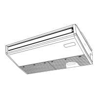
Mitsubishi Electric PCA-A24KA User Manual

Mitsubishi Electric PCA-A24KA
36 pages
To Next Page IconTo Next Page
Page #1 background imageLoading...
Page #1 background image
SERVICE MANUAL
SPLIT-TYPE, HEAT PUMP AIR CONDITIONERS
SPLIT-TYPE, AIR CONDITIONERS
No. OCH455
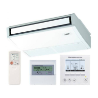
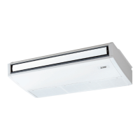
INDOOR UNIT
REMOTE CONTROLLER
CONTENTS
1. REFERENCE MANUAL
...................................
2
2. SAFETY PRECAUTION
...................................
3
3. PART NAMES AND FUNCTIONS
....................
4
4. SPECIFICATIONS
............................................
6
5. NOISE CRITERION CURVES
..........................
8
6. OUTLINES AND DIMENSIONS
.......................
9
7. WIRING DIAGRAM
.........................................
11
8. REFRIGERANT SYSTEM DIAGRA
.............
12
9. TROUBLESHOOTING
...................................
13
10. SPECIAL FUNCTION
.....................................
28
11. DISASSEMBLY PROCEDURE
.......................
31
ON/OFF
TEMP.
Indoor unit
[Model names] [Service Ref.]
PCA-A24KA
PCA-A24KA
PCA-A30KA
PCA-A30KA
PCA-A36KA
PCA-A36KA
PCA-A42KA
PCA-A42KA
March 2009
NOTE:
• This manual describes only
service data of the indoor
units.
• RoHS compliant products
have <G> mark on the
spec name plate.
PARTS CATALOG (OCB455)
Model name
indication

Questions and Answers:

Mitsubishi Electric PCA-A24KA Specifications

General IconGeneral
BrandMitsubishi Electric
ModelPCA-A24KA
CategoryAir Conditioner
LanguageEnglish

Summary

Safety Precaution

2-1. Always Observe for Safety

Essential safety guidelines to follow before performing maintenance.

2-2. Cautions Related to New Refrigerant

Specific safety precautions for handling R410A refrigerant.

Specifications

4-1. General Unit Specifications

Lists detailed specifications for PCA-A24KA, PCA-A30KA, PCA-A36KA models.

PCA-A42KA Specifications

Provides detailed specifications for the PCA-A42KA model.

Wiring Diagram

Model-Specific Wiring Diagrams

Provides wiring schematics for different PCA models.

Refrigerant System Diagram

Model-Specific Refrigerant Flow Diagrams

Illustrates refrigerant flow for cooling and heating for different PCA models.

Troubleshooting

9-2. Malfunction Diagnosis by Remote Controller

Procedure for using the remote controller to diagnose malfunctions.

9-3. Self-Diagnosis Action Table

Table detailing error codes, causes, and countermeasures for self-diagnosis.

9-4. Troubleshooting by Inferior Phenomena

Guides troubleshooting for issues not indicated by specific error codes.

9-5. Emergency Operation

Instructions for operating the unit in emergency mode when controls fail.

9-6. How to Check the Parts

Methods for testing key components like thermistors and motors.

Disassembly Procedure

Related product manuals