EasyManua.ls Logo

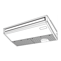
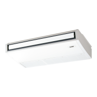
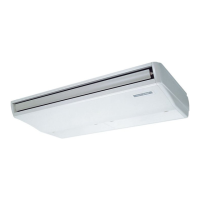
Mitsubishi Electric PCA-A24KA4 User Manual

Mitsubishi Electric PCA-A24KA4
36 pages
To Next Page IconTo Next Page
Page #1 background imageLoading...
Page #1 background image
SERVICE MANUAL
SPLIT-TYPE, HEAT PUMP AIR CONDITIONERS
SPLIT-TYPE, AIR CONDITIONERS
No. OCH484
INDOOR UNIT
CONTENTS
1. REFERENCE MANUAL
...................................
2
2. SAFETY PRECAUTION
...................................
3
3. PART NAMES AND FUNCTIONS
....................
4
4. SPECIFICATIONS
............................................
7
5. NOISE CRITERION CURVES
..........................
9
6. OUTLINES AND DIMENSIONS
......................
10
7. WIRING DIAGRAM
.........................................
12
8. REFRIGERANT SYSTEM DIAGRAM
............
13
9. TROUBLESHOOTING
...................................
14
10. SPECIAL FUNCTION
.....................................
28
11. DISASSEMBLY PROCEDURE
.......................
31
ON/OFF
TEMP.
COOL
DRY
AUTO
FAN
HEAT
Indoor unit
[Model names] [Service Ref.]
PCA-A24KA4
PCA-A24KA4
PCA-A30KA4
PCA-A30KA4
PCA-A36KA4
PCA-A36KA4
PCA-A42KA4
PCA-A42KA4
November 2010
NOTE:
• This manual describes only
service data of the indoor
units.
• RoHS compliant products
have <G> mark on the
spec name plate.
PARTS CATALOG (OCB484)
Model name
indication
33223
WIRED REMOTE
CONTROLLER
(Option)
IR WIRELESS REMOTE
CONTROLLER (Option)
Question and Answer IconNeed help?

Do you have a question about the Mitsubishi Electric PCA-A24KA4 and is the answer not in the manual?

Mitsubishi Electric PCA-A24KA4 Specifications

General IconGeneral
Cooling Capacity2.5 kW
Heating Capacity3.2 kW
Power Supply220-240 V, 50 Hz
RefrigerantR410A
Outdoor Unit Dimensions (HxWxD)550mm x 780mm x 285mm

Summary

Safety Precautions

General Safety Rules

Essential safety rules for accessing terminals and electrical circuits.

R410A Refrigerant Handling Cautions

Specific precautions for the safe handling and use of R410A refrigerant.

Part Names and Functions

Unit Specifications

Wiring Diagrams

Refrigerant System Diagram

Troubleshooting Guide

Summary of Self-Diagnosis Actions

Overview of self-diagnosis error codes and recommended service actions for troubleshooting.

Malfunction Diagnosis Using Remote Controllers

Procedures for diagnosing unit malfunctions through remote controller interface.

Detailed Error Code Reference Tables

Tables detailing specific error codes detected by indoor and outdoor units.

Detailed Self-Diagnosis Actions

Detailed guide for diagnosing and resolving specific error codes like P1, P2, P4, P5.

Error Codes for Protection and Pipe Temperature

Explains error codes P6 and P8 related to protection modes and pipe temperature anomalies.

Error Codes for Transmission and Water Leakage

Details error codes P9, PA, E0, E4 for pipe temperature, water leakage, and communication issues.

Error Codes for Communication and Control Issues

Covers error codes E3, E5, E6, E7, Fb, E1, E2 for communication failures and controller faults.

Emergency Operation Activation and Use

Guides on how to activate and utilize the emergency operation mode for the unit.

Component Check Procedures

Test Point Diagram

Switch and Jumper Wire Functions

Disassembly Procedure

Related product manuals