J
Joseph JacksonAug 1, 2025
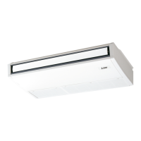
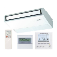
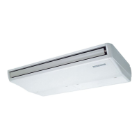
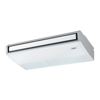
What to do if the Mitsubishi Electric PCA-RP71HAQ Air Conditioner trouble is not reoccurring and logged?
- CChristine ColemanAug 1, 2025
If the trouble with your Mitsubishi Electric Air Conditioner is not reoccurring but is logged, it may be due to temporary defects. These can include the activation of protection devices in the refrigerant circuit (including the compressor), poor wiring connections, or electrical noise. To address this, re-check the reported symptom, and inspect the installation environment, refrigerant level, weather conditions at the time of the issue, and related wiring. After completing these checks, reset the error code logs and restart the unit. This indicates that there are no apparent abnormalities in the electrical components, controller boards, or remote controller.