SERVICE MANUAL
Notes:
• This manual describes
service data of the indoor
units only.
• RoHS compliant products
have <G> mark on the
spec name plate.
CONTENTS
1. REFERENCE MANUAL
...................................
2
2. SAFETY PRECAUTION
...................................
3
3. PARTS NAMES AND FUNCTIONS
.................
4
4. SPECIFICATIONS
...........................................
10
5. NOISE CRITERION CURVES
.........................11
6. OUTLINES AND DIMENSIONS
...................... 12
7. WIRING DIAGRAM
.........................................13
8. REFRIGERANT SYSTEM DIAGRAM
............
14
9. TROUBLESHOOTING
....................................
15
10. SPECIAL FUNCTION
.....................................
29
11. DISASSEMBLY PROCEDURE
.......................
32
Indoor unit
[Model Name] [Service Ref.]
PARTS CATALOG (OCB580)
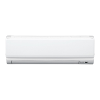
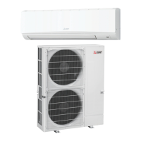
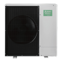
INDOOR UNIT
PKA-A12HA6
PKA-A12HA6
PKA-A18HA6
PKA-A18HA6
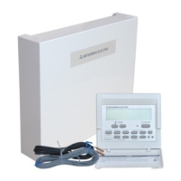
WIRED REMOTE
CONTROLLER
(Option)
IR WIRELESS REMOTE
CONTROLLER (Option)
December 2014
No. OCH580