Do you have a question about the Mitsubishi Electric PKA-A24KA6 and is the answer not in the manual?
| Series | PKA |
|---|---|
| Cooling Capacity | 2.5 kW |
| Heating Capacity | 3.2 kW |
| Coefficient of Performance (COP) | 3.61 |
| Refrigerant | R410A |
| Power Supply | 220-240V, 50Hz |
| Weight (Indoor Unit) | 9 kg |
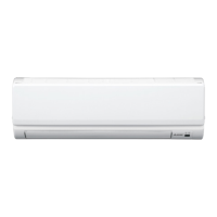
| Type | Wall Mounted |
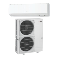
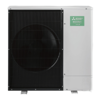
| Outdoor Unit Dimensions (HxWxD) | 550x800x290 mm |
| Noise Level (Outdoor Unit) | 50 dB(A) |
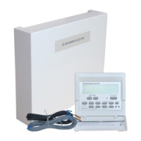
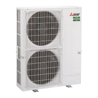
Outlines outdoor unit service manuals and optional remote controllers for various models.
Essential safety guidelines for handling refrigerants and electrical components.
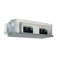
Identifies and describes the components of the indoor unit.
Lists technical specifications for various indoor unit models.
Presents sound pressure level data across different frequencies.
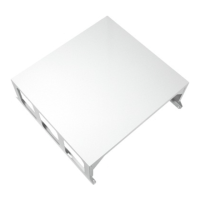
Provides physical dimensions and mounting details for indoor units.
Illustrates the electrical connections for the indoor unit.
Shows the flow of refrigerant through the system components.
Guides on diagnosing and resolving unit malfunctions and errors.
Explains advanced operational features like rotation and stage cut-in.
Step-by-step instructions for safely dismantling the indoor unit for maintenance.
Lists panel, heat exchanger, and functional components, indicating RoHS compliance.