Do you have a question about the Mitsubishi Electric PKA-A36KA6.TH and is the answer not in the manual?
| Type | Heat Pump |
|---|---|
| Cooling Capacity | 3.6 kW |
| Refrigerant | R410A |
| Power Source | 220-240 V, 50 Hz |
| Noise Level (Outdoor Unit) | 50 dB(A) |
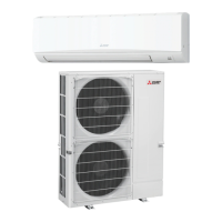
| Outdoor Unit Dimensions (HxWxD) | 550x800x300 mm |
Essential safety rules before starting any service work.
Specific safety guidelines for handling R410A refrigerant.
Overview of self-diagnosis and actions for recurring issues.
Methods for diagnosing malfunctions, check codes, symptoms, and tables.
Detailed table of check codes, causes, and countermeasures.
Details on specific errors (P6, P8, P9, PA, E0-E7, etc.).
Step-by-step guide to remove the front panel.
Steps to remove indoor and wireless remote controller boards.