EasyManua.ls Logo

Mitsubishi Electric PKFY-P12NHMU-E User Manual

Mitsubishi Electric PKFY-P12NHMU-E
24 pages
To Next Page IconTo Next Page
Page #1 background imageLoading...
Page #1 background image
TECHNICAL & SERVICE MANUAL
CONTENTS
1. PART NAMES AND FUNCTIONS
..........
2
2. SPECIFICATION
.....................................
4
3. OUTLINES AND DIMENSIONS
..............
6
4. WIRING DIAGRAM
.................................
7
5. REFRIGERANT SYSTEM DIAGRAM
..........
8
6. MICROPROCESSOR CONTROL
...........
9
7. TROUBLESHOOTING
..........................
14
8. DISASSEMBLY PROCEDURE
.............
21
Indoor unit
[Model names] [Service Ref.]
PKFY-P12NHMU-E
PKFY-P12NHMU-E
PKFY-P15NHMU-E
PKFY-P15NHMU-E
PKFY-P18NHMU-E
PKFY-P18NHMU-E
No. OCH460
INDOOR UNIT
SPLIT-TYPE, HEAT PUMP AIR CONDITIONERS
R22R410A
Note:
This manual describes
only service data of the
indoor units.
RoHS compliant products
have <G> mark on the
spec name plate.
April 2009
PARTS CATALOG (OCB460)
Question and Answer IconNeed help?

Do you have a question about the Mitsubishi Electric PKFY-P12NHMU-E and is the answer not in the manual?

Mitsubishi Electric PKFY-P12NHMU-E Specifications

General IconGeneral
BrandMitsubishi Electric
ModelPKFY-P12NHMU-E
CategoryAir Conditioner
LanguageEnglish

Summary

1 PART NAMES AND FUNCTIONS

Indoor unit

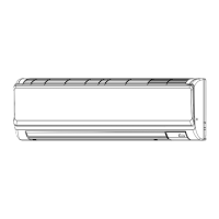
Details the components and functions of the indoor unit.

Wireless remote controller

Explains the functions and displays of the wireless remote.

2 SPECIFICATION

2-1. Specifications

Provides detailed technical specifications for different models.

2-2. Electrical parts specifications

Lists electrical components, their symbols, and specifications.

2-3. Sound levels

Presents sound level data for various operating conditions.

2-4. NC curves

Shows noise criterion (NC) curves for different models and fan speeds.

4 WIRING DIAGRAM

LED on indoor board for service

Explains the meaning and function of LEDs on the indoor service board.

6 MICROPROCESSOR CONTROL

6-1. COOL OPERATION

Details control logic and operation for cooling mode.

6-2. DRY OPERATION

Explains control logic and operation for dry mode.

6-3. FAN OPERATION

Describes control logic and operation for fan-only mode.

6-4. HEAT OPERATION

Details control logic and operation for heating mode.

6-5. AUTO OPERATION [AUTOMATIC COOL/HEAT CHANGE OVER OPERATION]

Explains automatic mode change logic between cool and heat.

7 TROUBLESHOOTING

7-1. HOW TO CHECK THE PARTS

Provides methods for checking various internal components for faults.

7-2. Function of Dip switch

Explains the function of dip switches for mode and setting configurations.

Address and Pair No. Settings

Details how to set addresses and pair remote controllers.

7-3. TEST POINT DIAGRAM

Illustrates test points on circuit boards for diagnostics.

8 DISASSEMBLY PROCEDURE

1. REMOVING THE LOWER SIDE OF THE INDOOR UNIT FROM THE INSTALLATION PLATE

Procedure to detach the lower side of the indoor unit from the mounting plate.

2. REMOVING THE FRONT PANEL

Step-by-step guide to removing the front panel of the unit.

3. REMOVING THE INDOOR CONTROLLER BOARD AND WIRELESS CONTROLLER BOARD

Instructions for removing the main controller and wireless receiver boards.

4. REMOVING THE ELECTRICAL BOX

Steps to remove the electrical box containing wiring and components.

5. REMOVING THE NOZZLE ASSEMBLY (with VANE and VANE MOTOR) AND DRAIN HOSE

Procedure for removing the nozzle assembly, vane motor, and drain hose.

6. REMOVING THE INDOOR FAN MOTOR AND THE LINE FLOW FAN

Instructions for removing the fan motor and fan components.

7. REMOVING THE VANE MOTOR

Steps for removing the vane motor unit and its components.

8. REMOVING THE LIQUID PIPE THERMISTOR AND GAS PIPE THERMISTOR

Procedure for removing the liquid and gas pipe thermistor sensors.

9. REMOVING THE HEAT EXCHANGER AND LEV

Instructions for removing the heat exchanger and linear expansion valve.

10. REMOVING THE ROOM TEMPERATURE THERMISTOR

Steps for removing the room temperature thermistor.

Related product manuals