Do you have a question about the Mitsubishi Electric PKFY-P15NLMU-E.TH and is the answer not in the manual?
| Brand | Mitsubishi Electric |
|---|---|
| Model | PKFY-P15NLMU-E.TH |
| Category | Air Conditioner |
| Language | English |
Covers safe handling of R410A refrigerant, including piping, oil, tools, and general safety measures.
Specific cautions for servicing and a list of essential tools for R410A refrigerant.
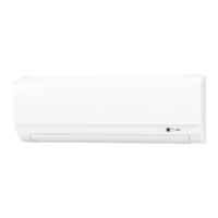
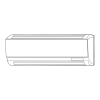
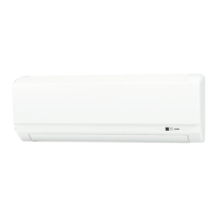
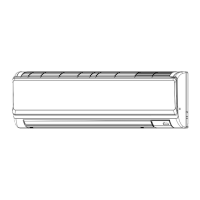
Identifies and illustrates the various parts of the indoor unit.
Lists the functions supported by the wired remote controller (PAR-40MAA) for different models.
Details button functions, LCD display elements, and the remote controller's menu structure.
Describes the interface, display modes, icons, and specific settings for the wireless remote controller.
Provides performance data like cooling/heating capacity and physical details like dimensions and weight.
Lists specifications for electrical parts such as thermistors, motors, fuses, and valves.
Presents noise data across various frequency bands for different indoor unit models.
Shows the physical dimensions of the indoor units and required space for installation.
Illustrates the electrical connections for the indoor unit, including component labels.
Details the control logic for temperature adjustment and fan speed in Cool mode.
Details the control logic for temperature adjustment and fan speed in Dry mode.
Details the control logic for fan-only mode operation and drain pump.
Details the control logic for temperature adjustment and fan speed in Heat mode.
Details the control logic for automatic cool/heat changeover operation.
Describes the behavior of the drain pump and float switch when the unit is stopped.
Guides on checking thermistors, motors, and drain pump for proper function and resistance.
Details thermistor characteristics and troubleshooting for the linear expansion valve (LEV).
Provides troubleshooting steps for the DC fan motor, including power supply and wiring checks.
Addresses troubleshooting for locked LEV mechanisms and faulty wiring connections.
Explains the purpose and settings of various DIP switches on the control boards.
Identifies key test points on the indoor controller board for diagnostic purposes.
Step-by-step instructions for removing the unit's front panel and electrical box covers.
Instructions for removing address boards, controller boards, wireless remote boards, and LEDs.
Procedures for detaching the fan motor, nozzle assembly, and drain hose.
Steps for removing the heat exchanger, LEV, and pipe/room temperature thermistors.