Do you have a question about the Mitsubishi Electric PKFY-P12NLMU-E.TH and is the answer not in the manual?
| Brand | Mitsubishi Electric |
|---|---|
| Model | PKFY-P12NLMU-E.TH |
| Category | Air Conditioner |
| Language | English |
General safety guidelines for R410A refrigerant systems.
Specific safety precautions to be followed during service operations.
Procedures and precautions for adding refrigerant to the system.
Recommended tools for servicing R410A refrigerant systems.
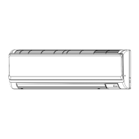
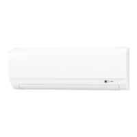
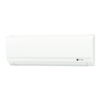
Identification and description of components of the indoor unit.
Overview of the wired remote controller and its functions.
Explanation of the buttons and layout of the remote controller.
Description of the icons and information displayed on the remote controller screen.
Technical data and performance characteristics of the indoor units.
Noise level data presented in octave band frequencies for model PKFY-P04NLMU-E.
Noise level data presented in octave band frequencies for model PKFY-P06NLMU-E.
Noise level data presented in octave band frequencies for model PKFY-P08NLMU-E.
Noise level data presented in octave band frequencies for model PKFY-P12NLMU-E.
Noise level data presented in octave band frequencies for model PKFY-P15NLMU-E.
Noise level data presented in octave band frequencies for model PKFY-P18NLMU-E.
Physical dimensions and installation space requirements for specific models.
Physical dimensions and installation space requirements for specific models.
Wiring connections for specific indoor unit models.
Wiring connections for specific indoor unit models.
Wiring connections for specific indoor unit models.
Diagram illustrating the refrigerant circuit for specific models.
Diagram illustrating the refrigerant circuit for specific models.
Diagram illustrating the refrigerant circuit for specific models.
Details on how the microprocessor controls the unit during cooling mode.
Function to prevent frequent compressor restarts and manage temperature control.
How the fan operates based on remote controller settings and conditions.
Operation control of the drain pump in COOL or DRY modes.
Control of vane position for airflow direction and restrictions.
Temperature control logic for the DRY operation mode.
Fan operation control for the DRY mode based on compressor conditions.
Drain pump operation in DRY mode, similar to COOL mode.
Vane operation settings for DRY mode are the same as COOL mode.
Fan speed adjustment based on remote controller settings.
Drain pump control logic for FAN operation mode.
Vane control during FAN operation, similar to COOL mode.
Temperature adjustment function for preventing restarts in HEAT mode.
Fan operation based on remote controller settings and various heating modes.
Controls fan speed during HEAT operation and heat standby.
Indoor fan operation in LOW mode after auxiliary heater turns off.
Indoor fan operation in EXTRA LOW when temp adjustment changes to OFF.
Indoor fan stops during heat defrosting mode.
Drain pump control logic for HEAT operation mode.
Vane position control and restrictions during HEAT operation.
Setting initial operation mode based on room temperature.
Conditions for switching between HEAT and COOL modes in AUTO.
Operation in COOL mode within AUTO operation.
Operation in HEAT mode within AUTO operation.
Drain pump operation when the unit is stopped.
Procedures for checking the functionality and resistance of key components.
Details on the function and settings of various DIP switches.
Diagrams showing test points on electronic boards for diagnostics.
Step-by-step guide to removing the front panel and corner box.
Procedure for removing the electrical box covers and disconnecting wires.
Steps to remove electronic boards like controller and address boards.
Procedure for removing the nozzle assembly and drain hose.
Steps to remove the vane motors (upper and lower).
Procedure for removing the indoor fan motor and line flow fan.
Steps to remove pipe thermistors and disconnect their connectors.
Procedure to remove the heat exchanger and linear expansion valve.
Steps to remove the room temperature thermistor.