TECHNICAL & SERVICE MANUAL
CONTENTS
1. TECHNICAL CHANGES .........................2
2. SAFETY PRECAUTION
..........................
3
3. PART NAMES AND FUNCTIONS
..........
5
4. SPECIFICATION
...................................
13
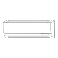
5. OUTLINES AND DIMENSIONS
............
15
6. WIRING DIAGRAM
...............................
16
7. REFRIGERANT SYSTEM DIAGRAM
........
19
8. TROUBLESHOOTING
..........................
19
9. DISASSEMBLY PROCEDURE
.............
28
Indoor unit
[Model names] [Service Ref.]
No. OCH418
REVISED EDITION-C
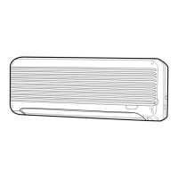
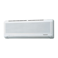
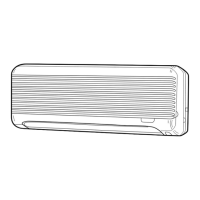
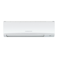
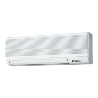
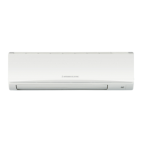
INDOOR UNIT
SPLIT-TYPE, HEAT PUMP AIR CONDITIONERS
R410A
Note:
• This manual describes only
service data of the indoor
units.
• RoHS compliant products
have <G> mark on the
spec name plate.
December 2012
Model name
indication
PARTS CATALOG (OCB418)
PKFY-P15VBM-E
PKFY-P15VBM-ER2
PKFY-P15VBM-ER3
PKFY-P20VBM-E
PKFY-P20VBM-ER1
PKFY-P20VBM-ER2
PKFY-P20VBM-ER3
PKFY-P25VBM-E
PKFY-P25VBM-ER1
PKFY-P25VBM-ER2
PKFY-P25VBM-ER3
Revision:
• PKFY-P15/20/25VBM-ER3
have been added in
REVISED EDITION-C.
• Some descriptions have
been modified.
• Please void OCH418
REVISED EDITION-B.
PKFY-P15VBM-E
PKFY-P20VBM-E
PKFY-P25VBM-E