EasyManua.ls Logo

Mitsubishi Electric PLFY Series User Manual

Mitsubishi Electric PLFY Series
56 pages
To Next Page IconTo Next Page
Page #1 background imageLoading...
Page #1 background image
PARTS CATALOG (TCB124)
SPLIT-TYPE, HEAT PUMP AIR CONDITIONERS
No. TCH124
REVISED EDITION-A
August 2023
Grille model
[Model name]
PLP-41EAEU
Indoor unit
[Model names] [Service Ref.]
PLFY-WL06NEMU-E
PLFY-WL08NEMU-E
PLFY-WL12NEMU-E
PLFY-WL15NEMU-E
PLFY-WL18NEMU-E
PLFY-WL24NEMU-E
PLFY-WL30NEMU-E
PLFY-WL36NEMU-E
PLFY-WL48NEMU-E
PLFY-WL06NEMU-E.TH
PLFY-WL08NEMU-E.TH
PLFY-WL12NEMU-E.TH
PLFY-WL15NEMU-E.TH
PLFY-WL18NEMU-E.TH
PLFY-WL24NEMU-E.TH
PLFY-WL30NEMU-E.TH
PLFY-WL36NEMU-E.TH
PLFY-WL48NEMU-E.TH
TCH124 is void.
Revision:
Some descriptions have been
revised in REVISED EDITION-A.
TECHNICAL
&
SERVICE
MANUAL
CONTENTS
1. SAFETY PRECAUTION
..........................
2
2. PARTS NAMES AND FUNCTIONS
........
3
3. SPECIFICATIONS
...................................
4
4. 4-WAY AIRFLOW SYSTEM
..................
10
5. OUTLINES AND DIMENSIONS
............
13
6. WIRING DIAGRAM
...............................
14
7.
REFRIGERANT SYSTEM DIAGRAM
......
15
8.
MICROPROCESSOR CONTROL
.
......
.....
15
9. TROUBLESHOOTING
..........................
22
10. DISASSEMBLY PROCEDURE
.............
29
11. REMOTE CONTROLLER
......................
36
INDOOR UNIT
Model name
indication for
MAIN UNIT
Model name
indication for GRILLE

Other manuals for Mitsubishi Electric PLFY Series

Question and Answer IconNeed help?

Do you have a question about the Mitsubishi Electric PLFY Series and is the answer not in the manual?

Mitsubishi Electric PLFY Series Specifications

General IconGeneral
BrandMitsubishi Electric
ModelPLFY Series
CategoryAir Conditioner
LanguageEnglish

Summary

Safety Precautions

Symbol Explanations

Explains the meaning of warning and caution symbols used in the manual.

Water Handling Safety

Safety guidelines specific to units that handle water.

Parts Names and Functions

Indoor Unit Components

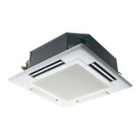
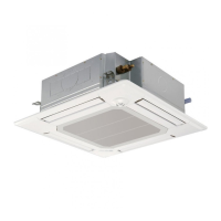
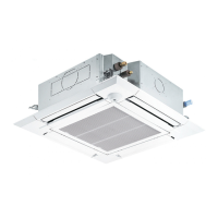
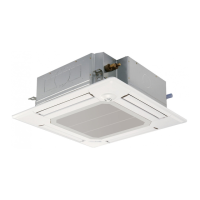
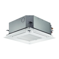
Identifies and describes the components of the indoor unit.

Wired Remote Controller Functions

Lists and explains functions supported by wired remote controllers.

Specifications Overview

General Specifications

Detailed technical specifications for various models of indoor units.

Electrical Parts Specifications

Specifications for electrical components like motors, fuses, and terminals.

Sound Pressure Levels

Sound pressure levels for different fan speeds and models.

NC Curves

Noise criteria (NC) curves for octave band sound pressure levels.

4-Way Airflow System

Air Outlet Placement and Settings

Instructions on setting airflow direction patterns and dip switches.

Duct Hole and Fresh Air Intake

Dimensions and procedures for cutting duct holes and intake.

Duct Fan Operation

Details on connecting and operating the unit with a booster fan.

Fresh Air Intake Characteristics

Graphs showing fresh air intake vs. static pressure for different configurations.

Outlines and Dimensions

Installation Dimensions and Clearances

Detailed diagrams showing unit dimensions, mounting, and required clearances.

Wiring Diagram

Indoor Unit Wiring Schematic

Electrical wiring diagram for the indoor unit, including component legends.

Refrigerant System Diagram

Refrigerant Circuit Overview

Diagram illustrating the refrigerant circuit and sensor locations.

Microprocessor Control

Cool Operation Control

Explanation of the cool mode operation and remote control functions.

Drying Operation Control

Details on the drying mode operation and its control parameters.

Fan Operation Control

Description of fan-only operation modes and fan speed settings.

Heat Operation Control

Explanation of heat mode operation and related controls.

Auto Operation Control

Information on automatic cool/heat changeover operation.

Stopped Unit Control Mode

Control mode behavior when the unit is stopped.

Troubleshooting

Part Checking Procedures

Procedures for checking various internal components using a multimeter.

DIP Switch Functions

Explanation of DIP switch settings for unit configuration and functions.

Test Point Diagram

Diagram showing test points on the indoor controller board for diagnostics.

Disassembly Procedure

Removing the Filter

Step-by-step guide to remove and replace the unit's air filter.

Removing the Electrical Box Cover

Instructions for safely removing the electrical box cover.

Removing the Indoor Controller Board

Procedure for detaching and removing the main circuit board for servicing.

Remote Controller

Remote Controller Functions

Overview of the remote controller interface and button functions.

Error Information Display

How to view and interpret error codes displayed on the remote controller.

Service Menu Navigation

Accessing and navigating the service menu for advanced settings.

Test Run Operations

Instructions for performing test runs of the unit's operations.

Function Setting Configuration

Guide to configuring various unit functions via the remote controller.

Error History Logging

How to view and clear the unit's error history logs.

Self-Diagnosis Procedure

Procedure for performing self-diagnosis on the unit.

Remote Controller Check

Steps to diagnose issues with the remote controller itself.

Related product manuals