EasyManua.ls Logo

Mitsubishi Electric PLFY-P05NFMU-E User Manual

Mitsubishi Electric PLFY-P05NFMU-E
32 pages
To Next Page IconTo Next Page
Page #1 background imageLoading...
Page #1 background image
Indoor unit
[Model Name] [Service Ref.]
PLFY-P05NFMU-E.TH
PLFY-P08NFMU-E.TH
PLFY-P12NFMU-E.TH
PLFY-P15NFMU-E.TH
PLFY-P18NFMU-E.TH
PLFY-P05NFMU-E
PLFY-P08NFMU-E
PLFY-P12NFMU-E
PLFY-P15NFMU-E
PLFY-P18NFMU-E
R410A
TECHNICAL & SERVICE MANUAL
March 2018
Notes:
7KLs PDQXDO GesFULEes seUYLFe
GDtD oI tKe LQGooU XQLts oQO\
5o+6 FoPSOLDQt SUoGXFts
KDYe *! PDUN oQ sSeF
QDPe SODte
63/,77<3( +($7 3803 $,5 &2N',7,2N(56
No. OCH604
REVISED EDITION-A
5eYLsLoQ:
0oGLILeG LQ :$< $,5
)/2: 6<67(0 LQ 5(9,6('
(',7,2N$
6oPe GesFULStLoQs KDYe EeeQ
PoGLILeG
2&+ Ls YoLG
INDOOR UNIT
0oGeO QDPe
LQGLFDtLoQ
CONTENTS
1. SAFETY PRECAUTION
..........................
2
2. PARTS NAMES AND FUNCTIONS
........
4
3. SPECIFICATIONS
.................................
12
4. 4-WAY AIR FLOW SYSTEM
.................
14
5. OUTLINES AND DIMENSIONS
............
16
6. WIRING DIAGRAM
...............................
17
7.
REFRIGERANT SYSTEM DIAGRAM
......
18
8. TROUBLESHOOTING
..........................
19
9. DISASSEMBLY PROCEDURE
.............
27
PARTS CATALOG (OCB604)
Question and Answer IconNeed help?

Do you have a question about the Mitsubishi Electric PLFY-P05NFMU-E and is the answer not in the manual?

Mitsubishi Electric PLFY-P05NFMU-E Specifications

General IconGeneral
BrandMitsubishi Electric
ModelPLFY-P05NFMU-E
CategoryAir Conditioner
LanguageEnglish

Summary

SAFETY PRECAUTION

CAUTIONS RELATED TO NEW REFRIGERANT

Provides essential warnings regarding the use of new refrigerants.

SERVICE CAUTIONS

Details important precautions for performing service operations.

PARTS NAMES AND FUNCTIONS

INDOOR UNIT COMPONENTS

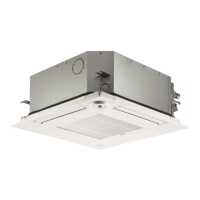
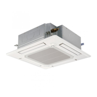
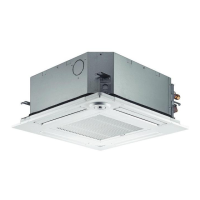
Identifies and describes the parts of the indoor unit.

WIRED REMOTE CONTROLLERS

Explains the functions and operation of the wired remote controllers.

WIRELESS REMOTE CONTROLLER

Details the functions and operation of the wireless remote controller.

SPECIFICATIONS

UNIT SPECIFICATIONS

Lists the detailed technical specifications for the air conditioning units.

ELECTRICAL PARTS SPECIFICATIONS

Details the specifications of electrical components used in the units.

AIR FLOW SYSTEM

FRESH AIR INTAKE

Covers fresh air intake location and airflow characteristics.

AIRFLOW CHARACTERISTICS

Provides data on fresh air intake volume and static pressure.

DUCT FAN OPERATION

Explains the operation of the unit in conjunction with a duct fan.

HORIZONTAL VANE ADJUSTMENT

Details the procedure for fixing the horizontal vane position.

OUTLINES AND DIMENSIONS

WIRING DIAGRAM

REFRIGERANT SYSTEM DIAGRAM

TROUBLESHOOTING

ERROR CODE COUNTERMEASURES

Provides countermeasures for error codes detected during test runs.

PART CHECK PROCEDURES

Details methods for checking the functionality of various unit parts.

DIP SWITCH FUNCTIONS

Explains the functions and settings of the unit's dip switches.

TEST POINT DIAGRAM

Illustrates key test points on the indoor controller board for diagnosis.

DISASSEMBLY PROCEDURE

Related product manuals