EasyManua.ls Logo

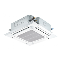
Mitsubishi Electric PLFY-P25VCM-E User Manual

Mitsubishi Electric PLFY-P25VCM-E
32 pages
To Next Page IconTo Next Page
Page #1 background imageLoading...
Page #1 background image
TECHNICAL & SERVICE MANUAL
Indoor unit
[Model names] [Service Ref.]
PLFY-P20VCM-E.TH
PLFY-P20VCM-E1.TH
PLFY-P25VCM-E.TH
PLFY-P25VCM-E1.TH
PLFY-P32VCM-E.TH
PLFY-P32VCM-E1.TH
PLFY-P40VCM-E.TH
PLFY-P40VCM-E1.TH
INDOOR UNIT
CONTENTS
1. TECHNICAL CHANGES·························2
2. SAFETY PRECAUTION··························2
3. PART NAMES AND FUNCTIONS··········6
4. SPECIFICATIONS···································8
5. 4-WAY AIR FLOW SYSTEM·················10
6. OUTLINES AND DIMENSIONS············12
7. WIRING DIAGRAM·······························13
8.
REFRIGERANT SYSTEM DIAGRAM
·····14
9. DISASSEMBLY PROCEDURE·············15
10. TROUBLESHOOTING··························18
11. PARTS LIST··········································25
12. RoHS PARTS LIST·······························29
SPLIT-TYPE, HEAT PUMP AIR CONDITIONERS
R407C
R22
R410A
Model name
indication
No.OC314
REVISED EDITION-C
Revision :
PLFY-P20/25/32/40VCM-
E1.TH are added in
REVISED EDITION-C.
Some descriptions have
been modified.
PLFY-P20VCM-E
PLFY-P25VCM-E
PLFY-P32VCM-E
PLFY-P40VCM-E
Please void OC314
REVISED EDITION-B.
July 2007
Note :
• RoHS compliant products
have <G> mark on spec
name plate.
For servicing RoHS compli-
ant products, refer to the
RoHS Parts List.
OC314C--1.qxp 07.7.19 8:42 AM Page 1

Other manuals for Mitsubishi Electric PLFY-P25VCM-E

Questions and Answers:

Mitsubishi Electric PLFY-P25VCM-E Specifications

General IconGeneral
TypeCeiling Cassette
Cooling Capacity2.5 kW
Heating Capacity3.2 kW
Power Supply220-240V, 50Hz
RefrigerantR410A
Indoor Unit Dimensions (HxWxD)245 x 570 x 570 mm
Coefficient of Performance (Heating)4.00

Summary

Series PLFY Ceiling Cassettes

Refrigerant Handling and Safety

R407C Refrigerant Precautions

Safe handling, piping, and lubricant advice for R407C refrigerant.

R407C Refrigerant Service Procedures

Recharging process, service tools, and essential steps for R407C refrigerant.

R410A Refrigerant Precautions

Safe handling, piping, and tool recommendations for R410A refrigerant.

R410A Refrigerant Service Procedures

Charging methods, service tools, and critical cautions for R410A refrigerant.

Part Names and Functions

Specifications

Wiring Diagram

Refrigerant System Diagram

Disassembly Procedure

Removing Air Intake Grille and Fan Guard

Step-by-step instructions for safely removing the air intake grille and fan guard.

Removing Panel and Electrical Parts

Procedure for removing the unit's panel and accessing internal electrical components.

Removing Temperature Sensors and Drain Pan

Instructions for removing room and pipe temperature detections, and the drain pan.

Removing Fan Motor

Detailed steps for safely disconnecting and removing the indoor unit's fan motor.

Removing Drain Pump and Heat Exchanger

Procedure for removing the drain pump, drain sensor, and the main heat exchanger.

Troubleshooting

Checking Component Resistance for Diagnosis

Guide to checking resistance of thermistors, motors, and valves for component diagnosis.

Linear Expansion Valve Operation and Troubleshooting

Explains linear expansion valve operation, pulse signals, and common troubleshooting steps.

Function of DIP Switch

Test Point Diagram

Related product manuals